
TPS65982 USB Type-C & USB PD Controller Power Switch & High Speed Multiplexer EVM
Texas Instruments
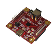
The TPS65982-EVM is a complete reference design for USB Type-C and Power Delivery applications. It allows the user to develop various power profiles and alternate modes such as DisplayPort and debug existing USB Type-C and Power Delivery systems.
Features:
- USB Type-C testing and verification
- USB Power Delivery testing and verification
- Application Emulation (Notebook, Dock, Dongle, Charger)
- Powered from single supply and bus-powered capable
This EVM was developed prior to the USB Power Delivery Specification change back in March 2016 and therefore does not have the native hardware to support the 5, 9, 15 and 20V rails. In order to follow the new source power rules please refer to TPS65982 Designs for Supporting Voltages in USB-PD 'Power Rules' or reference the TPS65981EVM.
| Distributor | SKU | Stock | MOQ | 1 | 10 | 50 | 100 | 1,000 | 10,000 |
|---|---|---|---|---|---|---|---|---|---|
| DigiKey | 296-42612-ND | 3 | 1 | $460.46 | $460.46 | $460.46 | $460.46 | $460.46 | $460.46 |
| Arrow North American Components | TPS65982-EVM | 2 | 1 | $261.48 | $227.39 | $227.39 | $227.39 | $227.39 | $227.39 |
| AVNET Asia Pacific | TPS65982-EVM | 0 | 1 | $36.46 | $35.44 | $34.03 | $33.58 | $33.58 | $33.58 |
| AVNET Europe | TPS65982-EVM | 0 | 1 | * $247.35 | * $244.17 | * $238.16 | * $235.21 | * $235.21 | * $235.21 |
| AVNET Express | TPS65982-EVM | 0 | 1 | $0.00 | $0.00 | $0.00 | $0.00 | $0.00 | $0.00 |
| element14 APAC | TPS65982-EVM | 38 | 1 | * $355.86 | * $355.86 | * $355.86 | * $355.86 | * $355.86 | * $355.86 |
| Farnell | TPS65982-EVM | 38 | 1 | * $303.03 | * $303.03 | * $303.03 | * $303.03 | * $303.03 | * $303.03 |
| Mouser Electronics | 595-TPS65982-EVM | 13 | 1 | $388.73 | $388.73 | $388.73 | $388.73 | $388.73 | $388.73 |
| Newark | TPS65982-EVM | 60 | 1 | $0.00 | $0.00 | $0.00 | $0.00 | $0.00 | $0.00 |
| RS Components | TPS65982-EVM | 0 | $375.16 | ||||||
| RS Components (APAC) | TPS65982-EVM | 0 | $620.05 | ||||||
| Texas Instruments | TPS65982-EVM | 15 | 1 | $199.00 | $199.00 | $199.00 | $199.00 | $199.00 | $199.00 |
| Verical Marketplace | TPS65982-EVM | 2 | 1 | $214.91 | $214.91 | $214.91 | $214.91 | $214.91 | $214.91 |
TPS65983 USB Type-C and USB PD Controller Power Switch and High-Speed Multiplexer Evaluation Module
Texas Instruments
The TPS65983EVM is a complete reference design for USB Type-C and Power Delivery applications. It allows the user to develop various power profiles and alternate modes such as Thunderbolt and DisplayPort and debug existing USB Type-C and Power Delivery systems.
Features:
- Thunderbolt™ 3 Alternate Mode capable
- USB Type-C testing and verification
- USB Power Delivery testing and verification
- Application Emulation (Notebook, Dock, Dongle, Charger)
- Powered from single supply and bus-powered capable
| Distributor | SKU | Stock | MOQ | 1 | 10 | 50 | 100 | 1,000 | 10,000 |
|---|---|---|---|---|---|---|---|---|---|
| AVNET Asia Pacific | TPS65983EVM | 0 | 1 | $0.00 | $0.00 | $0.00 | $0.00 | $0.00 | $0.00 |
| Mouser Electronics | N/A | 0 | |||||||
| Texas Instruments | TPS65983EVM | 3 | 1 | $149.00 | $149.00 | $149.00 | $149.00 | $149.00 | $149.00 |

18V, 10A Synchronous Step-Down Silent Switcher 2
Analog Devices Inc.
| Distributor | SKU | Stock | MOQ | 1 | 10 | 50 | 100 | 1,000 | 10,000 |
|---|---|---|---|---|---|---|---|---|---|
| DigiKey | 505-DC2560A-ND | 0 | 1 | $141.24 | $141.24 | $141.24 | $141.24 | $141.24 | $141.24 |
| Analog Devices Inc | DC2560A | 0 | $117.70 | $117.70 | $117.70 | $117.70 | $117.70 | $117.70 | |
| Arrow North American Components | DC2560A | 0 | 1 | $120.66 | $120.66 | $120.66 | $120.66 | $120.66 | $120.66 |
| element14 APAC | DC2560A | 5 | 1 | * $148.36 | * $148.36 | * $148.36 | * $148.36 | * $148.36 | * $148.36 |
| Farnell | DC2560A | 5 | 1 | * $135.21 | * $135.21 | * $135.21 | * $135.21 | * $135.21 | * $135.21 |
| Mouser Electronics | 584-DC2560A | 5 | 1 | $121.81 | $121.81 | $121.81 | $121.81 | $121.81 | $121.81 |
| Newark | DC2560A | 5 | 1 | $122.98 | $122.98 | $122.98 | $122.98 | $122.98 | $122.98 |
| Verical Marketplace | DC2560A | 9 | 1 | $116.46 | $116.46 | $116.46 | $116.46 | $116.46 | $116.46 |

LTM8074 1.2A Step-Down Silent Switcher µModule Regulator
Analog Devices Inc.
| Distributor | SKU | Stock | MOQ | 1 | 10 | 50 | 100 | 1,000 | 10,000 |
|---|---|---|---|---|---|---|---|---|---|
| DigiKey | 505-DC2753A-ND | 10 | 1 | $92.87 | $92.87 | $92.87 | $92.87 | $92.87 | $92.87 |
| Analog Devices Inc | DC2753A | 0 | $76.50 | $76.50 | $76.50 | $76.50 | $76.50 | $76.50 | |
| Arrow North American Components | DC2753A | 0 | 1 | $85.72 | $84.87 | $83.18 | $82.34 | $79.90 | $79.10 |
| element14 APAC | DC2753A | 1 | 1 | * $96.25 | * $96.25 | * $96.25 | * $96.25 | * $96.25 | * $96.25 |
| Farnell | DC2753A | 1 | 1 | * $75.57 | * $75.57 | * $75.57 | * $75.57 | * $75.57 | * $75.57 |
| Mouser Electronics | 584-DC2753A | 14 | 1 | $79.56 | $79.56 | $79.56 | $79.56 | $79.56 | $79.56 |
| Newark | DC2753A | 1 | 1 | $91.05 | $91.05 | $91.05 | $91.05 | $91.05 | $91.05 |
| Verical Marketplace | DC2753A | 51 | 1 | $75.70 | $75.70 | $75.70 | $75.70 | $75.70 | $75.70 |

LT8376 | 60V, 2A Silent Switcher Synchronous Step-Down LED Driver
Analog Devices Inc.
| Distributor | SKU | Stock | MOQ | 1 | 10 | 50 | 100 | 1,000 | 10,000 |
|---|---|---|---|---|---|---|---|---|---|
| DigiKey | 505-EVAL-LT8376-AZ-ND | 7 | 1 | $251.50 | $251.50 | $251.50 | $251.50 | $251.50 | $251.50 |
| Analog Devices Inc | EVAL-LT8376-AZ | 0 | $212.66 | $212.66 | $212.66 | $212.66 | $212.66 | $212.66 | |
| Arrow North American Components | EVAL-LT8376-AZ | 0 | 1 | ||||||
| element14 APAC | EVAL-LT8376-AZ | 3 | 1 | * $264.18 | * $264.18 | * $264.18 | * $264.18 | * $264.18 | * $264.18 |
| Farnell | EVAL-LT8376-AZ | 3 | 1 | * $240.78 | * $240.78 | * $240.78 | * $240.78 | * $240.78 | * $240.78 |
| Mouser Electronics | 584-EVAL-LT8376-AZ | 4 | 1 | $220.09 | $220.09 | $220.09 | $220.09 | $220.09 | $220.09 |
| Newark | EVAL-LT8376-AZ | 3 | 1 | $218.72 | $218.72 | $218.72 | $218.72 | $218.72 | $218.72 |
| Verical Marketplace | EVAL-LT8376-AZ | 1 | 1 | $37,410.58 | $37,410.58 | $37,410.58 | $37,410.58 | $37,410.58 | $37,410.58 |

LT8636 Demo Board | 42V, 5A Synchronous Step-Down Silent Switcher with 2.5μA Quiescent Current
Analog Devices Inc.
| Distributor | SKU | Stock | MOQ | 1 | 10 | 50 | 100 | 1,000 | 10,000 |
|---|---|---|---|---|---|---|---|---|---|
| DigiKey | 505-DC2918A-ND | 3 | 1 | $141.24 | $141.24 | $141.24 | $141.24 | $141.24 | $141.24 |
| Analog Devices Inc | DC2918A | 0 | $117.70 | $117.70 | $117.70 | $117.70 | $117.70 | $117.70 | |
| element14 APAC | DC2918A | 4 | 1 | * $148.36 | * $148.36 | * $148.36 | * $148.36 | * $148.36 | * $148.36 |
| Farnell | DC2918A | 4 | 1 | * $135.21 | * $135.21 | * $135.21 | * $135.21 | * $135.21 | * $135.21 |
| Mouser Electronics | 584-DC2918A | 1 | 1 | $122.42 | $122.42 | $122.42 | $122.42 | $122.42 | $122.42 |
| Newark | DC2918A | 4 | 1 | $122.98 | $122.98 | $122.98 | $122.98 | $122.98 | $122.98 |

LT8653S Demo Board | Dual Channel 2A, 42V, Synchronous Step-Down Silent Switcher with 6.2μA Quiescent Current
Analog Devices Inc.
| Distributor | SKU | Stock | MOQ | 1 | 10 | 50 | 100 | 1,000 | 10,000 |
|---|---|---|---|---|---|---|---|---|---|
| DigiKey | 505-DC2535A-ND | 1 | 1 | $138.47 | $138.47 | $138.47 | $138.47 | $138.47 | $138.47 |
| Analog Devices Inc | DC2535A | 0 | $117.70 | $117.70 | $117.70 | $117.70 | $117.70 | $117.70 | |
| Arrow North American Components | DC2535A | 2 | 1 | $32.56 | $32.56 | $32.56 | $32.56 | $32.56 | $32.56 |
| element14 APAC | DC2535A | 10 | 1 | * $149.31 | * $149.31 | * $149.31 | * $149.31 | * $149.31 | * $149.31 |
| Farnell | DC2535A | 1 | 1 | * $135.21 | * $135.21 | * $135.21 | * $135.21 | * $135.21 | * $135.21 |
| Mouser Electronics | 584-DC2535A | 3 | 1 | $121.81 | $121.81 | $121.81 | $121.81 | $121.81 | $121.81 |
| Newark | DC2535A | 10 | 1 | $138.80 | $138.80 | $138.80 | $138.80 | $138.80 | $138.80 |
| Verical Marketplace | DC2535A | 2 | 1 | $32.56 | $32.56 | $32.56 | $32.56 | $32.56 | $32.56 |

LT7182S | Dual Channel 6A, 20V, PolyPhase Step-Down Silent Switcher with Digital Power System Management
Analog Devices Inc.
| Distributor | SKU | Stock | MOQ | 1 | 10 | 50 | 100 | 1,000 | 10,000 |
|---|---|---|---|---|---|---|---|---|---|
| DigiKey | 505-DC2836A-ND | 9 | 1 | $122.45 | $122.45 | $122.45 | $122.45 | $122.45 | $122.45 |
| Analog Devices Inc | DC2836A | 0 | $101.65 | $101.65 | $101.65 | $101.65 | $101.65 | $101.65 | |
| Arrow North American Components | DC2836A | 0 | 1 | $113.89 | $112.75 | $110.51 | $109.41 | $106.16 | $105.09 |
| element14 APAC | DC2836A | 1 | 1 | * $123.23 | * $123.23 | * $123.23 | * $123.23 | * $123.23 | * $123.23 |
| Farnell | DC2836A | 2 | 1 | * $117.23 | * $117.23 | * $117.23 | * $117.23 | * $117.23 | * $117.23 |
| Mouser Electronics | 584-DC2836A | 2 | 1 | $105.72 | $105.72 | $105.72 | $105.72 | $105.72 | $105.72 |
| Newark | DC2836A | 2 | 1 | $120.20 | $120.20 | $120.20 | $120.20 | $120.20 | $120.20 |
| Verical Marketplace | DC2836A | 166 | 1 | $100.58 | $100.58 | $100.58 | $100.58 | $100.58 | $100.58 |
| Win Source | DC2836A | 4950 |

LT8652S Demo Board | Dual Channel 8.5A, 18V, Synchronous Step-Down Silent Switcher with 16µA Quiescent Current
Analog Devices Inc.
| Distributor | SKU | Stock | MOQ | 1 | 10 | 50 | 100 | 1,000 | 10,000 |
|---|---|---|---|---|---|---|---|---|---|
| DigiKey | 505-DC2523A-ND | 3 | 1 | $139.86 | $139.86 | $139.86 | $139.86 | $139.86 | $139.86 |
| Analog Devices Inc | DC2523A | 0 | $109.25 | $109.25 | $109.25 | $109.25 | $109.25 | $109.25 | |
| element14 APAC | DC2523A | 3 | 1 | * $147.16 | * $147.16 | * $147.16 | * $147.16 | * $147.16 | * $147.16 |
| Farnell | DC2523A | 3 | 1 | * $133.88 | * $133.88 | * $133.88 | * $133.88 | * $133.88 | * $133.88 |
| Mouser Electronics | 584-DC2523A | 4 | 1 | $113.63 | $113.63 | $113.63 | $113.63 | $113.63 | $113.63 |
| Newark | DC2523A | 3 | 1 | $114.38 | $114.38 | $114.38 | $114.38 | $114.38 | $114.38 |
| Verical Marketplace | DC2523A | 5 | 1 | $133.49 | $133.49 | $133.49 | $133.49 | $133.49 | $133.49 |

LT8415EDDB Demo Board | Ultralow Power Boost Converter with Dual Half-Bridge Switches
Analog Devices Inc.
| Distributor | SKU | Stock | MOQ | 1 | 10 | 50 | 100 | 1,000 | 10,000 |
|---|---|---|---|---|---|---|---|---|---|
| DigiKey | DC1449A-ND | 1 | 1 | $106.75 | $106.75 | $106.75 | $106.75 | $106.75 | $106.75 |
| Analog Devices Inc | DC1449A | 0 | $110.35 | $110.35 | $110.35 | $110.35 | $110.35 | $110.35 | |
| Arrow North American Components | DC1449A | 0 | 1 | $97.16 | $103.84 | $101.77 | $100.75 | $97.76 | $96.78 |
| Mouser Electronics | 584-DC1449A | 0 | 1 | $114.78 | $114.78 | $114.78 | $114.78 | $114.78 | $114.78 |
| Verical Marketplace | DC1449A | 160 | 1 | $75.00 | $82.19 | $80.00 | $78.95 | $78.95 | $78.95 |