|
|
Molex
1301370088
|
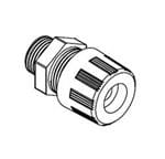
Molex
1300980069
|

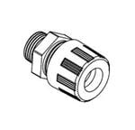
Molex
1300980082
|
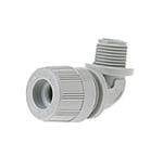
Molex
1300980197
|
Molex
1300980103
|
Molex
1300980109
|
Texas Instruments
SRC4192IDBRG4
|
Texas Instruments
SRC4193IDB
|
Texas Instruments
SRC4382IPFBR
|
C&K Components
CA01J12207HQ
|
| Price |
|
|
|
|
|
|
|
$5.85 |
|
|
|
| RoHS |
|
Not Compliant |
Compliant |
Compliant |
Compliant |
Not Compliant |
Compliant |
Compliant |
Yes |
Compliant |
Compliant |
| Lead Status |
|
|
No |
No |
No |
Yes |
No |
No |
Yes |
No |
No |
| # SRC Channels |
|
|
|
|
|
|
|
2 |
2 |
2 |
|
| Dynamic Range(dB) |
|
|
|
|
|
|
|
144 |
144 |
128 |
|
| Control Mode |
|
|
|
|
|
|
|
H/W |
SW (SPI) |
SW (SPI),H/W |
|
| Operating Temperature Range(C) |
|
|
|
|
|
|
|
-40 to 85 |
-40 to 85 |
-40 to 85 |
|
| Rating |
|
|
|
|
|
|
|
Catalog |
Catalog |
Catalog |
|
| Power Supply(V) |
|
|
|
|
|
|
|
3.3 |
3.3 |
1.8,3.3 |
|
| Package Group |
|
|
|
|
|
|
|
SSOP |
SSOP |
TQFP |
|
| Digital Supply (up to 5 V)(V) |
|
|
|
|
|
|
|
3 - 3.6 |
3 - 3.6 |
1.65 - 1.95,3 - 3.6 |
|
| Control Interface |
|
|
|
|
|
|
|
H/W |
SPI |
SPI,I2C |
|
| Package Size |
|
|
|
|
|
|
|
mm2 |
mm2 |
mm2 |
|
| Approx. Price (US$) |
|
|
|
|
|
|
|
5.20 | 1ku |
5.20 | 1ku |
6.00 | 1ku |
|
| Audio Data Format |
|
|
|
|
|
|
|
Normal,I2S,TDM |
Normal,I2S,TDM |
Normal,I2S |
|
| Sampling Rate(Max)(kHz) |
|
|
|
|
|
|
|
212 |
212 |
216 |
|
| THD+N(dB) |
|
|
|
|
|
|
|
-140 |
-140 |
-125 |
|
| Digital Audio Interface |
|
|
|
|
|
|
|
I2S,R,L,TDM |
I2S,R,L,TDM |
AES/EBU,S/PDIF |
|