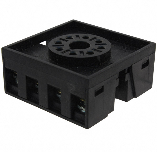
1422037-2

TE Connectivity 1422037-2

6-1393806-2

TE Connectivity 6-1393806-2

G6AU-274P-ST-US-DC5

Omron G6AU-274P-ST-US-DC5

2-1462038-0

TE Connectivity 2-1462038-0

1393808-6

TE Connectivity 1393808-6

3-1393816-4

TE Connectivity 3-1393816-4

1-1462051-6

TE Connectivity 1-1462051-6

6-1462039-4

TE Connectivity 6-1462039-4

1462039-8

TE Connectivity 1462039-8

G9SE-201

Omron G9SE-201

Price
RoHS Compliant Compliant
Lead Status Yes
Weight .141 20 .026 25 1.41 2.5 .026 .026
Coil Power Rating (DC) 450 823 100 1440 140 140 100
Coil Magnetic System Monostable, DC Monostable, DC Bistable, 1 Coil Monostable, DC Monostable, AC Monostable, DC Monostable, DC, Polarized Bistable, 1 Coil
Insulation Initial Dielectric Between Open Contacts 750 500 1000 500 1000 600 1000 1000
Contact Limiting Short-Time Current 3 .2 2 2 5 2 2 2
Contact Voltage Rating 125 36 220 125 250 220 220 220
Width 10.4 13 .224 .748 .748 7.2 6 6
Width Class (Mechanical) 10 – 12 mm 12 – 16 mm 0 – 6 mm 16 – 20 mm 16 – 20 mm 6 – 8 mm 0 – 6 mm 0 – 6 mm
Length Class (Mechanical) 14 – 16 mm 20 – 25 mm 0 – 10 mm 25 – 30 mm 25 – 30 mm 14 – 16 mm 0 – 10 mm 0 – 10 mm
Contact Switching Voltage (Max) 120 36 220 150 250 220 220 220
Insulation Initial Dielectric Between Contacts and Coil 1000 1000 1800 1000 1000 1800 1800
Insulation Initial Dielectric Between Coil/Contact Class 500 – 1000 V 500 – 1000 V 1500 V – 2500 VA 500 – 1000 V 500 – 1000 V 1500 V – 2500 VA 1500 V – 2500 VA
Product Type Relay Relay Relay Relay Relay Relay Relay Relay
Environmental Ambient Temperature (Max) 85 158 185 158 158 85 185 185
Contact Number of Poles 1 2 2 4 2 1 2 2
Contact Plating Material AgNi Alloy Gold Gold Gold Flash Gold Flash Gold Gold Gold
Insulation Initial Resistance 1000000 1000 1000000 1000 1000000 1000000 1000000
Termination Type Through Hole Solder Through Hole Plug-In/Solder Solder Terminals Through Hole Surface Mount
Length .606 .945 10 1.181 1.181 14.6 10
Height 11.5 30 5.8 30 40 10 5.65 5.65
Coil Resistance 320 110 203 7600 3200 145 145 58
Coil Power Rating Class 400 – 500 mW 600 – 800 mW 50 – 300 mW 600 – 800 mW 1 – 2 VA 50 – 300 mW 50 – 300 mW 50 – 300 mW
Contact Limiting Making Current 3 .2 2 2 5 2 2 2
Contact Limiting Continuous Current 3 2 2 2 5 2 2 2
Relay Type W11 Relay V23101 Cradle N Relay V23154/V23162 IM Relay Cradle N Relay V23154/V23162 Cradle W Relay V23005 HF3 Relay IM Relay IM Relay
Operating Temperature Range -40 – 85 -40 – 70 -40 – 85 -40 – 70 -40 – 70 -40 – 85 -40 – 85
Environmental Category of Protection RTIII RTI RTV RTI RTI RTIII RTV RTV
Contact Current Class 2 – 5 A 0 – 2 A 0 – 2 A 0 – 2 A 2 – 5 A 0 – 2 A 0 – 2 A 0 – 2 A
Contact Limiting Breaking Current 3 .2 2 2 5 2 2 2
Power Consumption 200 800 800 1150
Packaging Method Tube Box & Carton Tube Box & Carton Box & Carton Box & Carton Tube Reel
Height Class (Mechanical) 11 – 12 mm 25 – 30 mm 0 – 6 mm 25 – 30 mm 30 – 40 mm 9 – 10 mm 0 – 6 mm 0 – 6 mm
Coil Type Monostable Monostable Bistable Monostable Monostable Monostable Monostable Monostable
Actuating System DC AC/DC DC AC/DC AC DC DC DC
Contact Switching Load (Min) 10mA @ .02V .1mA @ .0001V .1mA @ .0001V .1mA @ .0001V
Mounting Type Printed Circuit Board Socket Printed Circuit Board Socket Printed Circuit Board Printed Circuit Board Printed Circuit Board
Relay Style W11 V23101 Signal Relay Cradle N Relay Cradle N Relay Cradle W Relay
Environmental Ambient Temperature Class 70 – 85°C 50 – 70°C 70 – 85°C 50 – 70°C 50 – 70°C 70 – 85°C 70 – 85°C 70 – 85°C
Coil Voltage Rating 12 5 5 4.5 2.4
Contact Material PdNi PdRu+Au Nickel Nickel PdRu+Au PdRu+Au
Terminal Type PCB-THT PCB-THT PCB-THT PCB-SMT PCB-SMT PCB-SMT
Contact Arrangement 1 Form C (CO) 2 Form C (2 CO) 4 Form C (CO) 1 Form C (CO) 2 Form C (2 CO) 2 Form C (2 CO)
Contact Current Rating 1 2 2 2 2 2
Performance Type Standard Standard Standard Standard Standard Standard
Contact Special Features Bifurcated/Twin Contacts Bifurcated/Twin Contacts Bifurcated/Twin Contacts Bifurcated/Twin Contacts Bifurcated/Twin Contacts
Additional Features Silver-Plated Terminals Narrow Gull Wing Short THT Pins Gull Wing
Insertion Loss (HF Parameter) -.03dB @ 100MHz -.03dB @ 100MHz -.03dB @ 100MHz -.03dB @ 100MHz
Isolation (HF Parameter) -18.8dB @ 900MHz -45dB @ 3GHz -18.8dB @ 900MHz -18.8dB @ 900MHz
Insulation Initial Dielectric Between Adjacent Contacts 1000 1000 1000 1000
Dimensions (L x W x H) (Approximate) .393 x .236 x .222 14.6 x 7.2 x 9.1 .393 x .236 x .222 .393 x .236 x .222
Voltage Standing Wave Ration (HF Parameter) 1.49 @ 900Mhz 1.07 @ 100MHz 1.49 @ 900Mhz 1.49 @ 900Mhz
Insulation Special Features 2500V Initial Surge Withstand Voltage between Contacts & Coil 1500V Initial Surge Withstand Voltage between Contacts & Coil 2500V Initial Surge Withstand Voltage between Contacts & Coil 2500V Initial Surge Withstand Voltage between Contacts & Coil