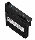
R10-E2Z4-V15.0K

TE Connectivity R10-E2Z4-V15.0K

KUL-11D55D-12

TE Connectivity KUL-11D55D-12

LSAW-2C-24B

TE Connectivity LSAW-2C-24B

SSRK-600A20

TE Connectivity SSRK-600A20

1850X

TE Connectivity 1850X

T9CP5A54-120

TE Connectivity T9CP5A54-120

EV200HDANA

TE Connectivity EV200HDANA

1393315-9

TE Connectivity 1393315-9

FC-325-1

TE Connectivity FC-325-1

FCA-325-CY2

TE Connectivity FCA-325-CY2

Price
RoHS
Lead Status
Contact Current Class 0 – 2 5 – 10 20 – 30 <50A
Product Length .949 1.55 50.3
Product Height 30.2 54.8 27.9
Length Class (Mechanical) 20 – 25 35 – 40 50 – 55 <60mm
Insulation Initial Dielectric Between Open Contacts 500 500 1500 1000
Insulation Initial Resistance 10000 100 1000
Power Relay Type Industrial Panel Plug-In Industrial Panel Plug-In Solid State Standard
Contact Material Ag AgCdO AgSnOlnO
Product Width .736 35.7 27.4
Contact Switching Load (Min) 1mA @ 12V 300mA @ 12V 1000mA @ 5V 1000mA @ 5VDC
Coil Power Rating DC 900 1600
Insulation Initial Dielectric Between Contacts & Coil 1000 1500 4000 2500
Relay Mounting Type Printed Circuit Board Panel Mount DIN Rail Quick Connect
Environmental Category of Protection RTI RTI RTII RTI
Terminal Type PCB-THT Solder Quick Connect Screw Terminals
Contact Voltage Rating 120 240 277
Coil Power Rating Class 800 – 1000 1500
Coil Magnetic System Monostable, DC Bistable, 2 Coils Polarized, Bistable Monostable, AC Monostable, DC Non-Polarized, Monostable Polarized, Monostable
Insulation Initial Dielectric Between Adjacent Contacts 1000 1500
Actuating System DC DC DC AC AC DC
Product Weight 40 3.386 9.87
Contact Special Features Bifurcated/Twin Contacts
Contact Arrangement 4 Form C (CO) 2 Form C (CO) 2 Form C, DPDT, 2 C/O 1 Form A (SPST-NO) 1 Form A, SPST-NO, 1 NO 1 Form C (CO) 1 Form X, SPST-NO 1 Form X (DM) 3 Form X 3 Form C, 3PDT, 3 C/O
Height Class (Mechanical) 30 – 40 20 – 35 40 – 50 mm
Coil Voltage Rating 115 12 26.5 120 32 – 95 12
Environmental Ambient Temperature (Max) 167 50 70 257
Packaging Method Package Package Tray/Box
Coil Special Features Sensitive Version Magnetic Latching UL Coil Insulation Class F
Coil Resistance 15000 90 1000 2800 141 70
Environmental Ambient Temperature Class 70 – 85 0 – 50 -40 – 70 105 – 125°C
Contact Number of Poles 4 2 2
Contact Current Rating (Max) 2 10 30
Width Class (Mechanical) 16 – 20 30 – 40 25 – 30 30 – 40 mm
Insulation Initial Dielectric Between Coil & Contact Class 500 – 1000 1000 – 1500 1500 – 2500
Operating Temperature Range -55 – 75 -45 – 50 -65 – 125 -30 – 80 -25 – 70 -70 – 125 -70 – 125
Contact Limiting Breaking Current 10 30 300
Contact Limiting Short-Time Current 10 30
Contact Limiting Making Current 10 30 300
Contact Limiting Continuous Current 10 30 180
Input Voltage 26.5 90 – 280 575
Coil Polarity Protection Diode Without
Coil Latching Double
Contact Current Rating 2 5 500 25 25
Coil Suppression Diode Without Without Without
Transistor Driver Without
Product Type Relay Relay Relay Relay Relay Relay
MOSFET Driver Without
Relay Type Military/Aerospace High Performance Protective Relay High Voltage High Current Relay HCR 150 Military/Aerospace Mid-Range Military/Aerospace Mid-Range
Enclosure Type Hermetically Sealed Hermetically Sealed Hermetically Sealed
Coil Power Rating (DC) 702 4100
Vibration 20G's, 10 – 2000Hz 10G's 30G's, 33 – 3000Hz
Mounting Type Plain Case Bottom Screw Studs, 6-32 UNC-2A Raised Vertical Flange Mount
Termination Type PC Pins
Shock 100G's, 6ms 50G's, 11ms 200G's, 6ms
Coil Power Measurement Milliwatts
Output Type AC
Output Current (Min) .15
Housing Style DIN Mount with Integral Heatsink
Output Voltage (Max) 660
R-Switch & slimSSR Relays Yes
Relay Termination Type Finger-Safe (IP20) Screw Clamps .25 x .032 Quick Connect Terminals
Switch Arrangement 1 Form A (SPST-NO)
Input Voltage Typical 90
Case Color Black
Output Switching Zero
Coupling Optical
Dimensions (L x W x H) (Approximate) 82.3 x 22.5 x 111.5 4.625 x 4.875 x 3
Output Current Rating .15 – 20
Output Voltage Rating (AC Relays) 48 – 660
Contact Arrangement (Additional Output) 1 Form B, SPST-NC, 1 N/C
Protection Function Paralleling
Frequency Adjustment 50 – 500
Mode of Operation Adjustable Pick-Up
Time Delay Without
Insulation Clearance Between Contact & Coil 3.18
Coil Power Rating AC 1600
Insulation Creepage Between Contact & Coil .25
Insulation Clearance Class 2.5 – 4
Insulation Creepage Class 5.5 – 8
Insulation Special Features 6000V Initial Surge Withstand Voltage between Contacts & Coil
Contact Switching Voltage (Max) 277 900
Auxiliary Contacts With Without Without
Economizer With
Termination Style Stud Terminals
High Voltage Connection (Power) Stud Terminals
Power Switching Yes
Contact Base Material Copper (Cu) AgSnO2 Silver Cadmium Oxide Silver Cadmium Oxide
Voltage (Max) 3920
RF Rated No
High Voltage Connection (Coil) Flying Leads
Length 2.92
Product Designation High Current Automotive Relays
Insulation Initial Dielectric Between Contacts and Coil 1000
Insulation Initial Dielectric Between Coil/Contact Class 500 – 1000 V
High Power Relays (<75A) Yes
Width 1.575
Current Rating (85°C) 130
Mounting Brackets With
Product Category Electromechanical Relays
Weight 7.766
Rated Coil Voltage 24
Height 45
Rated Voltage 24
Product Classification Relays - Automotive High Current Relays
Terminal Configuration Solder Hook Solder Hook
Coil Current .18
Frequency 400
Terminal Plating Tin-Lead Tin-Lead
Back EMF Suppression Without Without