|
|
|
|
|
|
|
|
|
|
||
| Price | |||||||||||
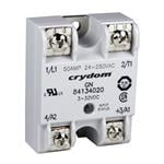
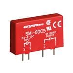
| RoHS | Compliant | Compliant | Compliant | Compliant | Compliant | Not Compliant | Compliant | Compliant | Compliant | Compliant | |
| Lead Status | Yes |
|
|
|
|
|
|
|
|
|
|
|
||
| Price | |||||||||||
| RoHS | Compliant | Compliant | Compliant | Compliant | Compliant | Not Compliant | Compliant | Compliant | Compliant | Compliant | |
| Lead Status | Yes |