|
|
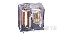
TE Connectivity
4-1393806-5
|
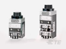
TE Connectivity
5-1472995-4
|

TE Connectivity
3-1423160-2
|

TE Connectivity
2-1755142-3
|

TE Connectivity
1472973-7
|
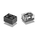
Omron
G6CK-1114P-US-DC24
|
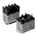
Omron
G7L-1A-TUB-CB-DC6
|
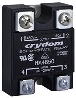
Crydom
HD60125-10
|
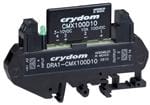
Crydom
DRA1-CX240A5
|
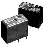
Omron
G5Q-1 DC5
|
| Price |
|
|
|
|
|
|
|
|
|
|
|
| RoHS |
|
|
|
|
|
|
Compliant |
Not Compliant |
Compliant |
Compliant |
Not Compliant |
| Lead Status |
|
|
|
|
|
|
|
No |
No |
|
|
| Height |
|
30 |
|
|
|
|
|
|
|
|
|
| Coil Resistance |
|
7600 |
|
|
|
|
|
|
|
|
|
| Coil Magnetic System |
|
Monostable, DC |
|
|
|
|
|
|
|
|
|
| Insulation Initial Dielectric Between Open Contacts |
|
500 |
|
|
|
|
|
|
|
|
|
| Weight |
|
20 |
|
|
|
|
|
|
|
|
|
| Terminal Type |
|
Plug-In |
|
|
|
|
|
|
|
|
|
| Length |
|
.945 |
|
|
|
|
|
|
|
|
|
| Width Class (Mechanical) |
|
12 – 16 mm |
|
|
|
|
|
|
|
|
|
| Length Class (Mechanical) |
|
20 – 25 mm |
|
|
|
|
|
|
|
|
|
| Insulation Initial Dielectric Between Contacts and Coil |
|
1000 |
|
|
|
|
|
|
|
|
|
| Insulation Initial Dielectric Between Coil/Contact Class |
|
500 – 1000 V |
|
|
|
|
|
|
|
|
|
| Product Type |
|
Relay |
|
|
|
|
|
|
|
|
|
| Environmental Category of Protection |
|
RTI |
|
|
|
|
|
|
|
|
|
| Contact Number of Poles |
|
2 |
|
|
|
|
|
|
|
|
|
| Width |
|
13 |
|
|
|
|
|
|
|
|
|
| Contact Limiting Short-Time Current |
|
.2 |
|
|
|
|
|
|
|
|
|
| Power Consumption |
|
800 |
|
|
|
|
|
|
|
|
|
| Packaging Method |
|
Box & Carton |
|
|
|
|
|
|
|
|
|
| Contact Limiting Continuous Current |
|
2 |
|
|
|
|
|
|
|
|
|
| Contact Voltage Rating |
|
36 |
|
|
|
|
|
|
|
|
|
| Performance Type |
|
Standard |
|
|
|
|
|
|
|
|
|
| Environmental Ambient Temperature (Max) |
|
158 |
|
|
|
|
|
|
|
|
|
| Height Class (Mechanical) |
|
25 – 30 mm |
|
|
|
|
|
|
|
|
|
| Contact Limiting Making Current |
|
.2 |
|
|
|
|
|
|
|
|
|
| Contact Limiting Breaking Current |
|
.2 |
|
|
|
|
|
|
|
|
|
| Contact Switching Voltage (Max) |
|
36 |
|
|
|
|
|
|
|
|
|
| Additional Features |
|
Silver-Plated Terminals |
|
|
|
|
|
|
|
|
|
| Contact Current Class |
|
0 – 2 A |
|
|
|
|
|
|
|
|
|
| Coil Power Rating (DC) |
|
268 |
|
|
|
|
|
|
|
|
|
| Operating Temperature Range |
|
-40 – 70 |
|
|
|
|
|
|
|
|
|
| Contact Arrangement |
|
2 Form C (CO) |
|
|
|
|
|
|
|
|
|
| Coil Type |
|
Monostable |
|
|
|
|
|
|
|
|
|
| Coil Power Rating Class |
|
600 – 800 mW |
|
|
|
|
|
|
|
|
|
| Insulation Initial Resistance |
|
10000000 |
|
|
|
|
|
|
|
|
|
| Relay Type |
|
Cradle N Relay V23154/V23162 |
|
|
|
|
|
|
|
|
|
| Contact Material |
|
Gold F |
|
|
|
|
|
|
|
|
|
| Contact Plating Material |
|
Gold |
|
|
|
|
|
|
|
|
|
| Contact Current Rating |
|
2 |
|
|
|
|
|
|
|
|
|
| Actuating System |
|
AC/DC |
|
|
|
|
|
|
|
|
|
| Mounting Type |
|
Printed Circuit Board |
|
|
|
|
|
|
|
|
|
| Relay Style |
|
Cradle N Relay |
|
|
|
|
|
|
|
|
|
| Termination Type |
|
Plug-In/Solder |
|
|
|
|
|
|
|
|
|
| Environmental Ambient Temperature Class |
|
50 – 70°C |
|
|
|
|
|
|
|
|
|