|
|
TE Connectivity
OMIH-SH-105L,394
|
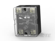
TE Connectivity
SSR-240D125
|
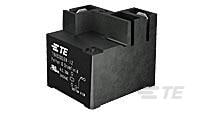
TE Connectivity
T9AP1D52-48
|
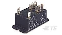
TE Connectivity
T92P7D42-24
|
TE Connectivity
T92P7D22-24
|
TE Connectivity
T92S7A12-24
|
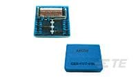
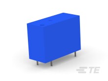
TE Connectivity
V23030H1017A104
|
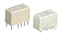
TE Connectivity
V23079B1201B301
|
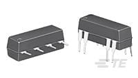
TE Connectivity
JWD-171-19
|
TE Connectivity
JWD-172-4
|
| Price |
|
|
|
|
|
|
|
|
|
|
|
| RoHS |
|
|
|
|
|
|
|
|
|
|
|
| Lead Status |
|
|
|
|
|
|
|
|
|
|
|
| Contact Current Class |
|
10 – 20 |
|
20 – 30 |
20 – 30 |
20 – 30 |
20 – 30 |
0 – 2 A |
0 – 2 A |
0 – 2 A |
0 – 2 A |
| Contact Current Rating (Max) |
|
16 |
|
30 |
30 |
30 |
30 |
|
|
|
|
| Height Class (Mechanical) |
|
20 – 25 |
|
25 – 30 |
25 – 30 |
25 – 30 |
30 – 40 |
10 – 11 mm |
9 – 10 mm |
7 – 8 mm |
7 – 8 mm |
| Coil Special Features |
|
Sensitive Version |
|
UL Coil Insulation Class F |
UL Coil Insulation Class F |
UL Coil Insulation Class F |
UL Coil Insulation Class F |
|
|
Coil Suppression Diode |
UL Coil Insulation |
| Contact Limiting Breaking Current |
|
16 |
|
30 |
40 |
40 |
40 |
3 |
2 |
.5 |
.5 |
| Coil Voltage Rating |
|
5 |
|
48 |
24 |
24 |
24 |
12 |
5 |
|
5 |
| Product Weight |
|
13 |
3.45 |
33 |
86 |
86 |
86 |
|
|
|
|
| Product Height |
|
20.6 |
|
27.9 |
26.4 |
26.4 |
1.209 |
|
|
|
|
| Insulation Initial Dielectric Between Coil & Contact Class |
|
4000 |
|
1500 – 2500 |
3500 – 4000 |
3500 – 4000 |
3500 – 4000 |
|
|
|
|
| Contact Voltage Rating |
|
250 |
|
277 |
277 |
277 |
277 |
250 |
220 |
20 |
10 |
| Insulation Creepage Between Contact & Coil |
|
8 |
|
.25 |
9.5 |
9.5 |
9.5 |
|
|
|
|
| Relay Mounting Type |
|
Printed Circuit Board |
Chassis Mount |
Panel Mount |
Panel Mount |
Panel Mount |
Printed Circuit Board |
|
|
|
|
| Contact Number of Poles |
|
1 |
|
1 |
2 |
2 |
2 |
4 |
2 |
1 |
1 |
| Terminal Type |
|
PCB-THT |
|
Quick Connect |
Quick Connect |
Quick Connect |
PCB-THT |
PCB-THT |
PCB-THT |
|
PCB-THT |
| Length Class (Mechanical) |
|
25 – 30 |
|
30 – 35 |
50 – 60 |
50 – 60 |
50 – 60 |
40 – 50 mm |
14 – 16 mm |
16 – 20 mm |
16 – 20 mm |
| Contact Switching Voltage (Max) |
|
250 |
|
277 |
600 |
600 |
600 |
250 |
220 |
100 |
28 |
| Coil Power Rating DC |
|
540 |
|
1000 |
1700 |
1700 |
|
|
|
|
|
| Coil Magnetic System |
|
Monostable, DC |
|
Monostable, DC |
Monostable, DC |
Monostable, DC |
Monostable, AC |
Monostable, DC |
Bistable, 2 Coils, Polarized |
Monostable, DC |
Monostable, DC |
| Insulation Creepage Class |
|
5.5 – 8 |
|
5.5 – 8 |
8 |
8 |
8 |
|
1.5 – 3 |
|
|
| Insulation Initial Resistance |
|
1000 |
|
1000 |
1000 |
1000 |
1000 |
1000 |
1000000 |
|
|
| Packaging Method |
|
Box & Carton |
|
Bundle |
Package |
Package |
Package |
Box & Carton |
Box & Carton |
Box & Tray |
Box & Tray |
| Product Width |
|
12.8 |
|
27.4 |
34.5 |
34.5 |
34.5 |
|
|
|
|
| Insulation Clearance Between Contact & Coil |
|
.098 |
|
3.18 |
.315 |
.315 |
.315 |
|
|
|
|
| Insulation Initial Dielectric Between Contacts & Coil |
|
5000 |
4000 |
2500 |
4000 |
4000 |
4000 |
|
|
|
|
| Insulation Initial Dielectric Between Open Contacts |
|
1000 |
|
1500 |
1500 |
1500 |
1500 |
1000 |
1000 |
250 |
175 |
| Environmental Category of Protection |
|
RTIII |
|
RTI |
RTI |
RTI |
RTII |
RTIII |
RTIII |
RTIII |
RTIII |
| Environmental Ambient Temperature (Max) |
|
70 |
|
185 |
185 |
185 |
65 |
110 |
85 |
85 |
85 |
| Contact Material |
|
AgSnO |
|
AgCdO |
AgCdO |
AgCdO |
AgCdO |
|
Ruthenium |
|
Ruthenium |
| Product Length |
|
1.15 |
|
32.5 |
2.051 |
2.051 |
52.3 |
|
|
|
|
| Contact Arrangement |
|
1 Form C (CO) |
1 Form A (SPST-NO) |
1 Form A (NO) |
2 Form A (NO) |
2 Form A (NO) |
2 Form A (NO) |
4 Form C (4 CO) |
2 Form C (CO) |
|
2 Form A (NO) |
| Coil Resistance |
|
48.5 |
|
2304 |
350 |
350 |
36 |
185 |
178 |
1200 |
2200 |
| Insulation Special Features |
|
10000V Initial Surge Withstand Voltage between Contacts & Coil |
|
6000V Initial Surge Withstand Voltage between Contacts & Coil |
6000V Initial Surge Withstand Voltage between Contacts & Coil |
6000V Initial Surge Withstand Voltage between Contacts & Coil |
6000V Initial Surge Withstand Voltage between Contacts & Coil |
|
2500V Initial Surge Withstand Voltage between Contacts & Coil |
|
|
| Width Class (Mechanical) |
|
12 – 16 |
|
25 – 30 |
30 – 40 |
30 – 40 |
30 – 40 |
30 – 40 mm |
6 – 8 mm |
6 – 8 mm |
6 – 8 mm |
| Contact Limiting Making Current |
|
16 |
|
30 |
40 |
40 |
40 |
3 |
2 |
.5 |
.5 |
| Contact Switching Load (Min) |
|
100mA @ 5V |
|
1000mA @ 5V |
500mA @ 12V |
500mA @ 12V |
500mA @ 12V |
|
10mA @ .2V |
10mA @ .01V |
10mA @ .01V |
| Environmental Ambient Temperature Class |
|
50 – 70 |
|
70 – 85 |
70 – 85 |
70 – 85 |
50 – 70 |
50 – 70°C |
70 – 85°C |
70 – 85°C |
70 – 85°C |
| Insulation Clearance Class |
|
0 – 2.5 |
|
2.5 – 4 |
5 – 8 |
5 – 8 |
5 – 8 |
|
0 – 2.5 |
|
|
| Contact Limiting Continuous Current |
|
16 |
|
30 |
40 |
40 |
40 |
2 |
2 |
.5 |
.5 |
| Contact Limiting Short-Time Current |
|
16 |
|
30 |
30 |
30 |
30 |
1 |
2 |
.5 |
.5 |
| Coil Power Rating Class |
|
500 – 600 |
|
800 – 1000 |
1500 |
1500 |
3 – 4 |
600 – 800 mW |
100 – 150 mW |
100 – 150 mW |
200 – 300 mW |
| Power Relay Type |
|
Standard |
Solid State |
Standard |
Standard |
Standard |
Standard |
|
|
|
|
| Dimensions (L x W x H) (Approximate) |
|
|
45 x 57.8 x 43.4 |
|
|
|
|
40.2 x 32.9 x 10.8 |
|
|
|
| Housing Style |
|
|
Hockey Puck |
|
|
|
|
|
|
|
|
| Output Type |
|
|
AC |
|
|
|
|
|
|
|
|
| Operating Temperature Range |
|
|
-30 – 80 |
|
|
|
|
-40 – 70 |
-40 – 85 |
-35 – 85 |
-35 – 85 |
| Input Voltage |
|
|
4 – 32 |
|
|
|
|
|
|
|
|
| Switch Arrangement |
|
|
1 Form A (SPST-NO) |
|
|
|
|
|
|
|
|
| Output Current (Min) |
|
|
.1 |
|
|
|
|
|
|
|
|
| Input Voltage Typical |
|
|
4 – 32 |
|
|
|
|
|
|
|
|
| Output Voltage (Max) |
|
|
280 |
|
|
|
|
|
|
|
|
| Output Current Rating |
|
|
.1 – 125 |
|
|
|
|
|
|
|
|
| Case Color |
|
|
Black |
|
|
|
|
|
|
|
|
| Output Switching |
|
|
Zero |
|
|
|
|
|
|
|
|
| Output Voltage Rating (AC Relays) |
|
|
24 – 280 |
|
|
|
|
|
|
|
|
| Coupling |
|
|
Optical |
|
|
|
|
|
|
|
|
| R-Switch & slimSSR Relays |
|
|
No |
|
|
|
|
|
|
|
|
| Relay Termination Type |
|
|
Screws |
|
|
|
|
|
|
|
|
| Insulation Initial Dielectric Between Adjacent Contacts |
|
|
|
|
2000 |
2000 |
2000 |
|
1000 |
|
|
| Coil Power Rating AC |
|
|
|
|
|
|
4 |
|
|
|
|
| Contact Plating Material |
|
|
|
|
|
|
|
Gold Flash |
Gold |
Ruthenium |
Ruthenium |
| Height |
|
|
|
|
|
|
|
.425 |
.386 |
8 |
8 |
| Insulation Initial Dielectric Between Contacts and Coil |
|
|
|
|
|
|
|
1000 |
1500 |
500 |
500 |
| Insulation Initial Dielectric Between Coil/Contact Class |
|
|
|
|
|
|
|
500 – 1000 V |
1000 V – 1500 VA |
0 – 500 V |
0 – 500 V |
| Product Type |
|
|
|
|
|
|
|
Relay |
Relay |
Relay |
Relay |
| Weight |
|
|
|
|
|
|
|
25 |
.0988 |
.0811 |
.0811 |
| Width |
|
|
|
|
|
|
|
32.9 |
7.2 |
.3 |
.3 |
| Coil Power Rating (DC) |
|
|
|
|
|
|
|
778 |
450 |
|
878 |
| Power Consumption |
|
|
|
|
|
|
|
800 |
200 |
50 – 288 |
50 – 288 |
| Termination Type |
|
|
|
|
|
|
|
Through Hole |
Through Hole |
Through Hole |
Through Hole |
| Length |
|
|
|
|
|
|
|
1.583 |
.571 |
.77 |
.799 |
| Performance Type |
|
|
|
|
|
|
|
Standard |
Standard |
|
Standard |
| Relay Style |
|
|
|
|
|
|
|
Card SN |
P2 V23079 Relay |
JWD/JWS Series Reed Relays |
JWD/JWS Series Reed Relays |
| Contact Special Features |
|
|
|
|
|
|
|
Bifurcated/Twin Contacts |
Bifurcated/Twin Contacts |
Reed Contacts |
Reed Contacts |
| Relay Type |
|
|
|
|
|
|
|
Card SN Relay V23030 |
P2 Relay V23079 |
JWD/JWS Series Reed Relay |
JWD/JWS Series Reed Relay |
| Coil Type |
|
|
|
|
|
|
|
Monostable |
Bistable, 2 Coils |
Monostable |
Monostable |
| Contact Current Rating |
|
|
|
|
|
|
|
2 |
.4 |
|
.5 |
| Actuating System |
|
|
|
|
|
|
|
DC |
DC |
DC |
DC |
| Mounting Type |
|
|
|
|
|
|
|
Printed Circuit Board |
Printed Circuit Board |
|
|
| Insulation Clearance Between Contact and Coil |
|
|
|
|
|
|
|
|
.051 |
|
|
| Voltage Standing Wave Ration (HF Parameter) |
|
|
|
|
|
|
|
|
1.4dB @ 900MHz |
|
|
| Insulation Creepage Between Contact and Coil |
|
|
|
|
|
|
|
|
.098 |
|
|


