|
|
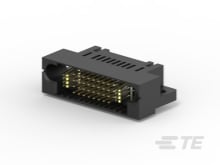
TE Connectivity
6-6450330-5
|
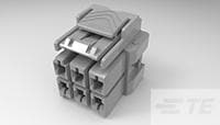
TE Connectivity
7-1971776-3
|
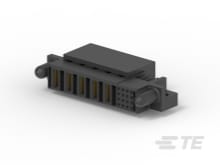
TE Connectivity
6450668-2
|
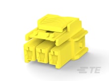
TE Connectivity
4-1971773-3
|
TE Connectivity
3-1971775-3
|
TE Connectivity
3-1971775-4
|
TE Connectivity
7-1971875-7
|
TE Connectivity
3-1971876-7
|
TE Connectivity
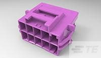
2-1971775-5
|
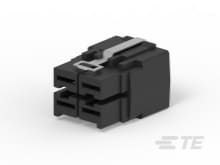
TE Connectivity
2173200-1
|
| Price |
|
|
|
|
|
|
|
|
|
|
|
| RoHS |
|
|
|
|
|
|
|
|
|
|
|
| Lead Status |
|
|
|
|
|
|
|
|
|
|
|
| PCB Mount Orientation |
|
Right Angle |
|
Right Angle |
|
|
|
|
|
|
Vertical |
| Number of Power Positions |
|
2 |
6 |
5 |
3 |
6 |
8 |
15 |
15 |
10 |
4 |
| Number of Rows |
|
4 |
2 |
|
1 |
2 |
2 |
3 |
3 |
2 |
2 |
| Housing Color |
|
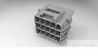
Black |
Black |
Black |
Yellow |
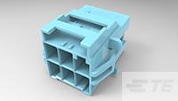
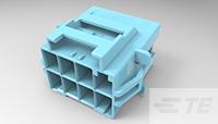
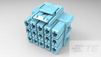
Blue |
Blue |
Black |
Blue |
Purple |
Black |
| Connector Mounting Type |
|
Board Mount |
Cable Mount |
Board Mount |
Cable Mount |
Panel |
Panel |
Panel |
Cable Mount |
Panel |
Cable Mount |
| Connector & Contact Terminates To |
|
Printed Circuit Board |
Wire & Cable |
Printed Circuit Board |
Wire & Cable |
Wire & Cable |
Wire & Cable |
Wire & Cable |
Wire & Cable |
Wire & Cable |
Wire & Cable |
| Number of Signal Positions |
|
40 |
|
16 |
|
|
|
|
|
|
|
| Contact Current Rating (Max) |
|
42 |
|
42 |
|
|
|
|
|
|
20 |
| Contact Retention |
|
Without |
Without |
Without |
Without |
Without |
Without |
Without |
Without |
Without |
With |
| Contact Mating Area Plating Thickness |
|
.076 |
|
30 |
|
|
|
|
|
|
76.2 |
| UL Flammability Rating |
|
UL 94V-0 |
UL 94V-0 |
UL 94V-0 |
UL 94V-0 |
UL 94V-0 |
UL 94V-0 |
UL 94V-0 |
UL 94V-0 |
UL 94V-0 |
UL 94V-0 |
| Contact Type |
|
Pin |
Receptacle |
Socket |
Receptacle |
Tab |
Tab |
Tab |
Receptacle |
Tab |
Socket |
| Glow Wire Rating |
|
High Temperature Part - Not Glow Wire |
High Temperature Part - Not Glow Wire |
High Temperature Part - Not Glow Wire |
Standard Part - Not Glow Wire |
Standard Part - Not Glow Wire |
Standard Part - Not Glow Wire |
High Temperature Part - Not Glow Wire |
Standard Part - Not Glow Wire |
Standard Part - Not Glow Wire |
Standard Part - Not Glow Wire |
| Packaging Method |
|
Tray |
Carton |
Tray |
Carton |
Carton |
Carton |
Carton |
Carton |
Carton |
Tray |
| Row-to-Row Spacing |
|
.1 |
8.1 |
|
|
8.1 |
8.1 |
.319 |
.319 |
8.1 |
.246 |
| Centerline (Pitch) |
|
2.54 |
6 |
7.62 |
6 |
6 |
6 |
6 |
6 |
6 |
7.8 |
| Connector System |
|
Board-to-Board |
Wire-to-Wire |
Board-to-Board |
Wire-to-Wire |
Wire-to-Wire |
Wire-to-Wire |
Wire-to-Wire |
Wire-to-Wire |
Wire-to-Wire |
Wire-to-Wire |
| Contact Mating Area Plating Material |
|
Noble Metal |
|
Gold |
|
|
|
|
|
|
Silver |
| Circuit Application |
|
Power & Signal |
Power |
Power & Signal |
Power |
Power |
Power |
Power |
Power |
Power |
Power |
| Housing Type |
|
Plug |
Plug |
Receptacle |
Plug |
Cap |
Cap |
Cap |
Plug |
Cap |
Receptacle |
| Termination Method to Printed Circuit Board |
|
Through Hole - Solder |
|
Through Hole - Press-Fit |
|
|
|
|
|
|
|
| Contact Termination Area Plating Material |
|
Tin |
|
Tin |
|
|
|
|
|
|
Silver |
| Operating Voltage |
|
60 |
600 |
60 |
600 |
600 |
600 |
600 |
600 |
600 |
60 |
| Housing Material |
|
High Temperature Thermoplastic |
Nylon |
High Temperature Thermoplastic |
PBT GF |
PBT GF |
PBT GF |
Nylon |
PBT GF |
PBT GF |
PBT GF |
| Number of Positions |
|
42 |
6 |
21 |
3 |
6 |
8 |
15 |
15 |
10 |
4 |
| Board-to-Board Configuration |
|
Right Angle |
|
Right Angle |
|
|
|
|
|
|
|
| Sealable |
|
No |
No |
No |
No |
No |
No |
No |
No |
No |
No |
| Product Type |
|
Header |
Housing |
Connector Assembly |
Housing |
Housing |
Housing |
Housing |
Housing |
Housing |
Receptacle |
| Operating Temperature Range |
|
-20 – 105 |
-55 – 150 |
-20 – 105 |
-67 – 221 |
-67 – 221 |
-67 – 221 |
-55 – 150 |
-67 – 221 |
-67 – 221 |
-40 – 125 |
| For Use With |
|
|
Receptacle (Socket) Contact |
|
Receptacle (Socket) Contact |
Tab Contact |
Tab Contact |
Tab Contact |
Receptacle (Socket) Contact |
Tab Contact |
|
| Agency/Standard Number |
|
|
E28476 |
|
E28476 |
E28476 |
E28476 |
E28476 |
E28476 |
E28476 |
|
| Agency/Standard |
|
|
UL |
|
UL |
UL |
UL |
UL |
UL |
UL |
|
| Contact Layout |
|
|
Matrix |
|
Inline |
Matrix |
Matrix |
Matrix |
Matrix |
Matrix |
|
| Circuit Identification Feature |
|
|
With |
|
With |
With |
With |
With |
With |
With |
|
| UL Rating |
|
|
Recognized |
|
Recognized |
Recognized |
Recognized |
Recognized |
Recognized |
Recognized |
|
| Termination Method to Wire & Cable |
|
|
Crimp |
|
Crimp |
Crimp |
Crimp |
Crimp |
Crimp |
Crimp |
Crimp |
| Keying |
|
|
C |
|
D |
C |
C |
C |
C |
B |
|
| Cable Exit Angle |
|
|
Straight |
|
Straight |
Straight |
Straight |
Straight |
Straight |
Straight |
|
| Panel Mount Feature |
|
|
Without |
|
Without |
With |
With |
With |
Without |
With |
|
| Panel Thickness |
|
|
|
|
|
1 – 2 |
1 – 2 |
1 – 2 |
|
1 – 2 |
|
| Panel Mount Feature Type |
|
|
|
|
|
Latches |
Latches |
Latches |
|
Latches |
|
| Height |
|
|
|
|
|
23.05 |
23.05 |
31.15 |
|
23.05 |
24.1 |
| PCB Mount Retention |
|
|
|
|
|
|
|
|
|
|
Without |
| Wire/Cable Size |
|
|
|
|
|
|
|
|
|
|
12 – 14 |
| Backwall/Post Interruptions |
|
|
|
|
|
|
|
|
|
|
Without |
| Insulation Resistance |
|
|
|
|
|
|
|
|
|
|
1000 |
| Contact Base Material |
|
|
|
|
|
|
|
|
|
|
Copper Alloy |
| Strain Relief |
|
|
|
|
|
|
|
|
|
|
Without |
| PCB Mount Alignment |
|
|
|
|
|
|
|
|
|
|
Without |
| Dielectric Withstanding Voltage |
|
|
|
|
|
|
|
|
|
|
750 |
| Mating Retention Type |
|
|
|
|
|
|
|
|
|
|
Locking Latch |
| Mating Retention |
|
|
|
|
|
|
|
|
|
|
With |
| Mating Alignment |
|
|
|
|
|
|
|
|
|
|
With |
| Packaging Quantity |
|
|
|
|
|
|
|
|
|
|
70 |
| Length |
|
|
|
|
|
|
|
|
|
|
.69 |
| Mating Alignment Type |
|
|
|
|
|
|
|
|
|
|
Polarization |


