|
|
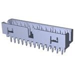
TE Connectivity
2007562-6
|
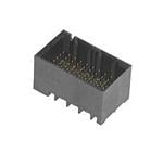
TE Connectivity
650072-000
|
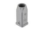
TE Connectivity
S02-10-R
|
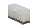
TE Connectivity
MTC100Q-SH1-R22
|
TE Connectivity
342A012-25/225-0
|
TE Connectivity
202A121-25/225-0
|
TE Connectivity
202D132-4/42-0
|
TE Connectivity
382A012-25/225-0
|
TE Connectivity
301A511-51-0
|
TE Connectivity
222A132-3-0
|
Price |
|
|
|
|
|
|
|
|
|
|
|
RoHS |
|
|
Compliant |
|
|
|
|
|
Compliant |
|
|
Lead Status |
|
|
|
|
|
|
|
|
No |
|
|
Port Matrix Configuration |
|
2 x 6 |
|
|
|
|
|
|
|
|
|
Tail Length |
|
3 |
|
|
|
|
|
|
|
|
|
PCB Thickness (Recommended) |
|
.059 |
|
|
|
|
|
|
|
|
|
Centerline (Pitch) |
|
.8 |
|
|
|
|
|
|
|
|
|
EMI Containment Feature Type |
|
External Springs |
|
|
|
|
|
|
|
|
|
Contact Mating Area Plating Thickness |
|
.76 |
|
|
|
|
|
|
|
|
|
Cage Material |
|
Nickel Silver |
|
|
|
|
|
|
|
|
|
Connector Mounting Type |
|
Board Mount |
|
|
|
|
|
|
|
|
|
Connector & Contact Terminates To |
|
Printed Circuit Board |
|
|
|
|
|
|
|
|
|
Connector System |
|
Cable-to-Board |
|
|
|
|
|
|
|
|
|
Included Lightpipe |
|
Yes |
|
|
|
|
|
|
|
|
|
Form Factor |
|
SFP+ |
|
|
|
|
|
|
|
|
|
Number of Positions |
|
240 |
|
|
|
|
|
|
|
|
|
UL Flammability Rating |
|
UL 94V-0 |
|
|
|
|
|
|
|
|
|
Heat Sink Compatible |
|
No |
|
|
|
|
|
|
|
|
|
Cage Type |
|
Stacked |
|
|
|
|
|
|
|
|
|
Included Heat Sink |
|
No |
|
|
|
|
|
|
|
|
|
Lightpipe Configuration |
|
Single Triangular (Inner) |
|
|
|
|
|
|
|
|
|
Contact Mating Area Plating Material |
|
Gold or Gold Flash over Palladium Nickel |
|
|
|
|
|
|
|
|
|
Circuit Application |
|
Signal |
|
|
|
|
|
|
|
|
|
Pluggable I/O Applications |
|
SFP+ |
|
|
|
|
|
|
|
|
|
Product Type |
|
Cage Assembly with Integrated Connector |
Splice |
Shield Terminator |
|
Molded Part |
|
|
Molded Part |
Molded Part |
|
Number of Ports |
|
12 |
|
|
|
|
|
|
|
|
|
Tail Plating Material |
|
Tin |
|
|
|
|
|
|
|
|
|
Data Rate (Max) |
|
16 |
|
|
|
|
|
|
|
|
|
PCB Mounting Style |
|
Through Hole Press-Fit |
|
|
|
|
|
|
|
|
|
Packaging Method |
|
Package |
Bag/Box |
|
|
|
|
|
|
Bag/Box |
|
Integrated Lightpipes |
|
Yes |
|
|
|
|
|
|
|
|
|
Operating Temperature Range |
|
-67 – 221 |
-55 – 150 |
|
|
-75 – 150 |
-75 – 150 |
-20 – 60 |
-75 – 150 |
-67 – 275 |
-55 – 135 |
Sealable |
|
No |
Yes |
|
|
|
|
|
|
|
|
Termination Method to Printed Circuit Board |
|
Through Hole - Press-Fit |
|
|
|
|
|
|
|
|
|
Terminal & Splice Style |
|
|
Splice |
|
|
|
|
|
|
|
|
Serrated |
|
|
No |
|
|
|
|
|
|
|
|
Support Style |
|
|
Non-Insulation Support |
|
|
|
|
|
|
|
|
Wire Size |
|
|
24 – 20 |
|
|
|
|
|
|
|
|
Government Qualified |
|
|
Yes |
No |
|
No |
No |
No |
No |
No |
No |
Overall Length |
|
|
34.93 |
19.1 |
|
|
|
|
|
|
|
Barrel Inside Diameter |
|
|
.067 |
|
|
|
|
|
|
|
|
Number of Serrations |
|
|
0 |
|
|
|
|
|
|
|
|
Barrel Type |
|
|
Closed Barrel |
|
|
|
|
|
|
|
|
Insulated |
|
|
Yes |
|
|
|
|
|
|
|
|
Splice Material |
|
|
Tin-Plated Copper |
|
|
|
|
|
|
|
|
Wire/Cable Type |
|
|
Insulated Wire |
|
|
|
|
|
|
|
|
Insulation Material |
|
|
Modified Polyvinylidene |
|
|
|
|
|
|
|
|
Heavy Duty |
|
|
No |
|
|
|
|
|
|
|
|
Splice Features |
|
|
Splice Kit |
|
|
|
|
|
|
|
|
Accessory Type |
|
|
Splice |
|
|
|
|
|
|
|
|
Splice Type |
|
|
In-Line Splice |
|
|
|
|
|
|
|
|
Shield Outside Diameter (Min) |
|
|
|
.17 |
|
|
|
|
|
|
|
Recovered Inside Diameter (Max) |
|
|
|
2.5 |
|
|
|
|
|
|
|
Jacket Outside Diameter |
|
|
|
.34 |
|
|
|
|
|
|
|
Wire Size Range |
|
|
|
22 |
|
|
|
|
|
|
|
MIL/NAS Specification (MIL-S-83519, NAS-1747) |
|
|
|
M83519/1 |
|
|
|
|
|
|
|
Temperature Indicator |
|
|
|
Yes |
|
|
|
|
|
|
|
Resistance Properties |
|
|
|
Immersion Protection |
|
|
|
|
|
|
|
Pre-Installed Lead |
|
|
|
No |
|
|
|
|
|
|
|
Expanded Inside Diameter (Min) |
|
|
|
.3 |
|
|
|
|
|
|
|
Temperature Indicator Type |
|
|
|
Thermochromic |
|
|
|
|
|
|
|
Inside Diameter Range (Body) |
|
|
|
|
|
.27 – .52 |
|
|
.24 – .52 |
6.6 – 19.8 |
|
Comment |
|
|
|
|
|
Use only with DR-25 tubing. |
|
|
Use only with DR-25 tubing. |
Contact Raychem for additional adhesive and/or cut off boot length information |
|
Special Requirements |
|
|
|
|
|
Flame Retarded |
|
|
Flame Retarded |
Flame Retarded |
|
Wire/Cable OD |
|
|
|
|
|
10 |
|
|
.35 |
.28 – .7 |
|
Wire/Cable Main Branch OD |
|
|
|
|
|
.35 |
|
|
4 |
7.2 – 11.8 |
|
Material Code |
|
|
|
|
|
25 |
|
|
25 |
51 |
|
Breakout Angle |
|
|
|
|
|
45 |
|
|
22.5 |
90 |
|
Material |
|
|
|
|
|
Modified Elastomer |
Modified Polyolefin |
Modified Elastomer |
Elastomeric Polymer Blend (EPB) |
Modified Polyolefin |
Power Cable Accessory |
|
|
|
|
|
No |
No |
No |
No |
No |
No |
Wire/Cable Sm Branch OD |
|
|
|
|
|
.18 |
|
|
.18 |
.28 – .46 |
|
Size Code |
|
|
|
|
|
12 |
|
|
12 |
11 |
|
Adhesive Options |
|
|
|
|
|
/225 Precoat |
/225 Precoat, -75 – 150°C (-103 – 302°F) |
/42 Precoat, -20 – 60°C (-4 – 140°F) |
/225 Precoat |
/164 Precoat |
S1006 Separate Adhesive, -55°C – 135°C (-67°F – 275°F) |
Molded Part Type |
|
|
|
|
|
Transition |
Molded Boot |
Molded Boot |
Transition |
Breakouts/Transitions |
Molded Boot |
Transition Type |
|
|
|
|
|
Y-Transition |
|
|
Y-Transition |
T-Transition |
|
Number of Branches/Legs |
|
|
|
|
|
2 |
|
|
2 |
3 |
|
Inside Diameter Range (Leg 1) |
|
|
|
|
|
6.9 – 13.2 |
|
|
3.3 – 6.6 |
.26 – .52 |
|
Adhesive Type |
|
|
|
|
|
Unicure Pre-Coated Epoxy Adhesive |
General Purpose Pre-Coat Adhesive |
Unicure Pre-Coated Epoxy Adhesive |
Hot-Melt Elastomeric Polymer |
Adhesive Purchased Separately |
Adhesive Code |
|
|
|
|
|
225 |
|
|
225 |
S1124 |
|
Adhesive Pre-Coat |
|
|
|
|
|
Yes |
Yes |
Yes |
Yes |
No |
No |
Material Systems Code |
|
|
|
|
|
25 |
25 |
10 |
25 |
20 |
10 |
Inside Diameter Range (Leg 2) |
|
|
|
|
|
.14 – .26 |
|
|
.13 – .26 |
6.6 – 13.2 |
|
Fluid/Chemical Resistance |
|
|
|
|
|
Long-term exposure at elevated temps |
Suitable for long term fluid exposure at elevated temperatures |
Suitable for occasional exposure to fluids |
Long-term exposure at elevated temps |
Suitable for occasional exposure to fluids |
Molded Part Shape |
|
|
|
|
|
45° Side-Breakout |
|
|
Y Shape |
T Shape |
|
Color |
|
|
|
|
|
Black |
|
|
Black |
Black |
|
Wire/Cable Outside Diameter |
|
|
|
|
|
|
.276 in |
12 mm |
|
|
12 mm |
Approved Standards |
|
|
|
|
|
|
BS-G-198-5-DE |
SAE AS I 81765/1, Type II |
|
|
BS-G-198-5-DA |
Cable Diameter Range |
|
|
|
|
|
|
5.3 – 17.8 |
6.6 – 14.7 |
|
|
.252 – .811 |
Lipped |
|
|
|
|
|
|
No |
Yes |
|
|
No |
Entry Size (Solid or Fixed Adapter) |
|
|
|
|
|
|
|
4 – 6 |
|
|
|
Entry Size (Spin Coupling Adapter) |
|
|
|
|
|
|
|
6 – 12 |
|
|
|
Shrink Ratio Type |
|
|
|
|
|
|
|
|
|
High |
|
Pliancy |
|
|
|
|
|
|
|
|
|
Flexible |
|
Resistant To |
|
|
|
|
|
|
|
|
|
Fluids |
|