|
|
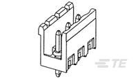
TE Connectivity
1-1776149-1
|
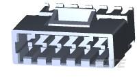
TE Connectivity
3-644812-6
|
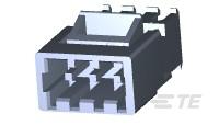
TE Connectivity
3-644814-3
|
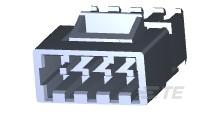
TE Connectivity
3-644814-4
|
TE Connectivity
1-1776132-1
|
TE Connectivity
1776133-2
|
TE Connectivity
1776133-7
|
TE Connectivity
1776133-8
|
TE Connectivity
3-644892-6
|
TE Connectivity
1776155-4
|


