|
|
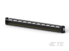
TE Connectivity
4-1827253-6
|
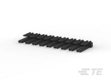
TE Connectivity
1744544-9
|
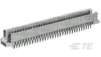
TE Connectivity
5650911-5
|
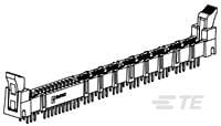
TE Connectivity
1651864-1
|
TE Connectivity
6650679-1
|
TE Connectivity
6643460-3
|
TE Connectivity
42973-2
|
TE Connectivity
42973-1
|
TE Connectivity
1825851-1
|
TE Connectivity
1-1969443-6
|
| Price |
|
|
|
|
|
|
|
|
|
|
|
| RoHS |
|
|
|
|
Compliant |
|
Compliant |
|
|
|
|
| Lead Status |
|
|
|
|
No |
|
No |
|
|
|
|
| Contact Design |
|
|
|
|
Multiple Contact Band/CROWN BAND |
|
|
|
|
|
|
| Contact Mating Area Plating Thickness |
|
|
|
|
29.92 |
|
30 |
|
|
|
|
| Contact Layout |
|
|
|
|
Staggered |
|
|
|
|
|
|
| Contact Termination Area Plating Finish |
|
|
|
|
Matte |
|
Matte |
|
|
|
|
| Width |
|
|
|
|
.3555 |
|
|
|
|
|
|
| PCB Thickness (Recommended) |
|
|
|
|
1.57 – 2.36 |
|
2.36 |
|
|
|
|
| Power Contact Centerline |
|
|
|
|
9.7 |
|
.508 |
|
|
|
|
| Accepts Card Thickness |
|
|
|
|
.093 |
|
|
|
|
|
|
| Operating Voltage |
|
|
|
|
250 |
|
250 |
|
|
|
|
| Housing Material |
|
|
|
|
Thermoplastic |
|
Thermoplastic |
|
|
|
|
| Housing Color |
|
|
|
|
Black |
|
Black |
|
|
|
|
| Agency/Standard Number |
|
|
|
|
UL 1977 |
|
|
|
|
|
|
| PCB Mount Retention |
|
|
|
|
Without |
|
With |
|
|
|
|
| Mating Alignment Type |
|
|
|
|
Keyed |
|
|
|
|
|
|
| Length |
|
|
|
|
148.22 |
|
|
|
|
|
|
| Height |
|
|
|
|
20 |
|
15 |
|
|
|
|
| UL Flammability Rating |
|
|
|
|
UL 94V-0 |
|
UL 94V-0 |
|
|
|
|
| Connector Mounting Type |
|
|
|
|
Board Mount |
|
Board Mount |
|
|
|
|
| Connector & Contact Terminates To |
|
|
|
|
Printed Circuit Board |
|
Printed Circuit Board |
|
|
|
|
| Contact Type |
|
|
|
|
Socket |
|
Socket |
|
|
|
|
| Termination Post &Tail Length |
|
|
|
|
.118 |
|
.159 – .199 |
|
|
|
|
| Number of Dual Positions |
|
|
|
|
10 |
|
0 |
|
|
|
|
| Contact Base Material |
|
|
|
|
Copper Alloy |
|
Phosphor Bronze |
|
|
|
|
| Contact Termination Area Plating Thickness |
|
|
|
|
120 |
|
100 |
|
|
|
|
| Card Slot Depth |
|
|
|
|
6 |
|
|
|
|
|
|
| Accepts Card Width |
|
|
|
|
126.64 |
|
|
|
|
|
|
| Agency/Standard |
|
|
|
|
CSA |
|
|
|
|
|
|
| For Use With |
|
|
|
|
Mates with Plug |
|
Printed Circuit Board |
|
|
|
|
| Number of Power Positions |
|
|
|
|
18 |
|
2 |
|
|
|
|
| End Caps |
|
|
|
|
With |
|
Without |
|
|
|
|
| CSA File Number |
|
|
|
|
1935071 |
|
|
|
|
|
|
| PCB Mount Alignment |
|
|
|
|
With |
|
Without |
|
|
|
|
| Housing Type |
|
|
|
|
Receptacle |
|
Receptacle |
|
|
|
|
| PCB Mount Orientation |
|
|
|
|
Vertical |
|
Vertical |
|
|
|
|
| Number of Rows |
|
|
|
|
2 |
|
2 |
|
|
|
|
| Number of Signal Positions |
|
|
|
|
20 |
|
8 |
|
|
|
|
| Mating Retention |
|
|
|
|
With |
|
Without |
|
|
|
|
| Special Features |
|
|
|
|
Custom Configurable |
|
|
|
|
|
|
| Connector System |
|
|
|
|
Board-to-Board |
|
Board-to-Board |
|
|
|
|
| Product Type |
|
|
|
|
Connector Assembly |
|
Connector Assembly |
|
|
|
|
| Termination Post & Tail Length |
|
|
|
|
3 |
|
5.08 |
|
|
|
|
| Number of Positions |
|
|
|
|
38 |
|
10 |
|
|
|
|
| Number of Single Positions |
|
|
|
|
10 |
|
|
|
|
|
|
| Centerline (Pitch) |
|
|
|
|
2.5 |
|
2.5 |
|
|
|
|
| Circuit Application |
|
|
|
|
Power & Signal |
|
Power & Signal |
|
|
|
|
| Packaging Quantity |
|
|
|
|
28 |
|
192 |
|
|
|
|
| Packaging Method |
|
|
|
|
Box & Carton |
|
Package |
|
|
|
|
| Termination Method to Printed Circuit Board |
|
|
|
|
Through Hole - Solder |
|
Through Hole - Press-Fit |
|
|
|
|
| Mating Alignment |
|
|
|
|
With |
|
With |
|
|
|
|
| Operating Temperature Range |
|
|
|
|
-67 – 221 |
|
-67 – 221 |
|
|
|
|
| Board-to-Board Configuration |
|
|
|
|
Right Angle |
|
|
|
|
|
|
| Contact Current Rating (Max) |
|
|
|
|
25 |
|
35 |
|
|
|
|
| Contact Termination Area Plating Material |
|
|
|
|
Tin |
|
Tin |
|
|
|
|
| Contact Mating Area Plating Material |
|
|
|
|
Gold |
|
Gold |
|
|
|
|
| Mating Retention Type |
|
|
|
|
Latch |
|
|
|
|
|
|
| Module Length |
|
|
|
|
|
|
26.8 |
|
|
|
|
| Mating & Unmating Configuration |
|
|
|
|
|
|
Hot Pluggable |
|
|
|
|
| Signal Contact Material |
|
|
|
|
|
|
Phosphor Bronze Alloy |
|
|
|
|
| Power Contact Material |
|
|
|
|
|
|
Phosphor Bronze Alloy |
|
|
|
|
| Contact Retention |
|
|
|
|
|
|
Without |
|
|
|
|
| Signal Contact Plating Material |
|
|
|
|
|
|
Select Gold |
|
|
|
|
| Selectively Loaded |
|
|
|
|
|
|
No |
|
|
|
|
| PCB Mount Retention Type |
|
|
|
|
|
|
Action/Compliant Tail |
|
|
|
|
| Power Contact Plating Material |
|
|
|
|
|
|
Select Gold |
|
|
|
|


