|
|
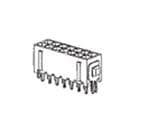
TE Connectivity
3-794680-2
|
TE Connectivity
1-794221-0
|
TE Connectivity
1-794222-0
|
TE Connectivity
5748678-2
|
TE Connectivity
5745171-1
|
TE Connectivity
5745172-1
|
TE Connectivity
5745172-2
|
TE Connectivity
K10P-11DT5-12
|
TE Connectivity
PT370012
|
TE Connectivity
R10-E1Y2-S800
|
| Price |
|
|
|
|
|
|
|
|
|
|
|
| RoHS |
|
Compliant |
|
|
|
Compliant |
|
|
|
|
|
| Lead Status |
|
No |
|
|
|
No |
|
|
|
|
|
| Number of Power Positions |
|
2 |
|
|
|
|
|
|
|
|
|
| Contact Termination Area Plating Finish |
|
Matte |
|
|
|
|
|
|
|
|
|
| CSA File Number |
|
LR7189 |
LR 7189 |
LR 7189 |
|
|
|
|
|
|
|
| CSA Rating |
|
Certified |
Certified |
Certified |
|
|
|
|
|
|
|
| PCB Mount Retention Type |
|
Boardlock |
|
|
|
|
|
|
|
|
|
| Connector System |
|
Wire-to-Board |
Wire-to-Wire |
Wire-to-Wire |
|
|
|
|
|
|
|
| Contact Current Rating (Max) |
|
5 |
10.5 |
10.5 |
|
|
|
|
15 |
10 |
3 |
| PCB Thickness (Recommended) |
|
1.57 |
|
|
|
|
|
|
|
|
|
| Insulation Diameter (Max) |
|
1.52 |
|
|
|
|
|
|
|
|
|
| Housing Material |
|
High Temperature Nylon |
|
|
|
|
|
|
|
|
|
| Housing Color |
|
Black |
|
|
|
|
|
|
|
|
|
| Agency/Standard Number |
|
E28476 |
|
|
|
|
|
|
|
|
|
| Connector Mounting Type |
|
Board Mount |
Cable Mount |
Cable Mount |
|
|
|
|
|
|
|
| Connector & Contact Terminates To |
|
Printed Circuit Board |
Wire & Cable |
Wire & Cable |
|
|
|
|
|
|
|
| Wire/Cable Size |
|
100.5 – 1022 |
22 – 18 |
20 – 16 |
|
|
|
|
|
|
|
| Number of Rows |
|
2 |
|
|
|
|
|
|
|
|
|
| Contact Retention |
|
Without |
|
|
|
|
|
|
|
|
|
| Contact Mating Area Plating Thickness |
|
2.54 – 7.62 |
.76 |
.76 |
|
|
|
|
|
|
|
| Multiple Contact Types |
|
Without |
|
|
|
|
|
|
|
|
|
| Operating Voltage |
|
250 |
600 |
600 |
|
|
|
|
|
|
|
| UL Flammability Rating |
|
UL 94V-0 |
|
|
|
|
|
|
|
|
|
| Agency/Standard |
|
CSA |
UL |
UL |
|
|
|
|
|
|
|
| Glow Wire Rating |
|
Standard Part - Not Glow Wire |
Standard Part - Not Glow Wire |
Standard Part - Not Glow Wire |
|
|
|
|
|
|
|
| Strain Relief |
|
Without |
|
|
|
|
|
|
|
|
|
| Packaging Quantity |
|
533 |
4500 |
5000 |
|
|
|
|
|
|
|
| Contact Type |
|
Pin |
Socket |
Pin |
|
|
|
|
|
|
|
| Contact Termination Area Plating Material |
|
Tin |
Tin |
Tin |
|
|
|
|
|
|
|
| Packaging Method |
|
Box & Tray |
Reel |
Reel |
|
|
|
|
Tray |
Carton & Tube |
Package |
| Number of Positions |
|
2 |
|
|
|
|
|
|
|
|
|
| PCB Mount Orientation |
|
Vertical |
|
|
|
|
|
|
|
|
|
| Row-to-Row Spacing |
|
3 |
|
|
|
|
|
|
|
|
|
| Boardlock Material |
|
Phosphor Bronze |
|
|
|
|
|
|
|
|
|
| Mating Retention Type |
|
Locking Tab |
|
|
|
|
|
|
|
|
|
| PCB Mount Retention |
|
With |
|
|
|
|
|
|
|
|
|
| Circuit Application |
|
Power |
Power |
Power |
|
|
|
|
|
|
|
| For Use With |
|
Receptacle Housing |
Plug Housing |
Plug or Cap Housing |
|
|
|
|
|
|
|
| Termination Post & Tail Length |
|
3.18 |
|
|
|
|
|
|
|
|
|
| Termination Post &Tail Length |
|
.125 |
|
|
|
|
|
|
|
|
|
| UL Rating |
|
Recognized |
Recognized |
Recognized |
|
|
|
|
|
|
|
| Housing Type |
|
Plug |
|
|
|
|
|
|
|
|
|
| Termination Method to Printed Circuit Board |
|
Through Hole - Solder |
|
|
|
|
|
|
|
|
|
| Mating Retention |
|
With |
|
|
|
|
|
|
|
|
|
| Mating Alignment |
|
With |
|
|
|
|
|
|
|
|
|
| Operating Temperature Range |
|
-40 – 221 |
-20 – 105 |
-67 – 221 |
|
|
|
|
-45 – 70 |
-40 – 70 |
-55 – 75 |
| Contact Termination Area Plating Thickness |
|
100 |
2.54 |
2.54 – 6.35 |
|
|
|
|
|
|
|
| Contact Mating Area Plating Material |
|
Tin |
Gold |
Gold |
|
|
|
|
|
|
|
| Centerline (Pitch) |
|
3 |
|
|
|
|
|
|
|
|
|
| VDE Tested |
|
Yes |
Yes |
Yes |
|
|
|
|
|
|
|
| Panel Mount Feature |
|
Without |
|
|
|
|
|
|
|
|
|
| Mating Alignment Type |
|
Polarization |
|
|
|
|
|
|
|
|
|
| Sealable |
|
No |
|
|
|
|
|
|
|
|
|
| Product Type |
|
Header |
Contact |
Contact |
|
|
|
|
|
|
|
| Contact Angle |
|
|
Straight |
Straight |
|
|
|
|
|
|
|
| Accepts Wire Insulation Diameter Range |
|
|
.059 – .094 |
.079 – .126 |
|
|
|
|
|
|
|
| Mating Pin Diameter |
|
|
1 |
1 |
|
|
|
|
|
|
|
| Termination Type |
|
|
Crimp |
Crimp |
|
|
|
|
|
|
|
| Underplate Material Thickness |
|
|
1.27 |
1.27 |
|
|
|
|
|
|
|
| Crimp Area Plating Thickness |
|
|
2.54 |
100 – 250 |
|
|
|
|
|
|
|
| Wire/Cable Type |
|
|
Discrete Wire |
Discrete Wire |
|
|
|
|
|
|
|
| Wire Contact Termination Area Plating Material |
|
|
Tin |
Tin |
|
|
|
|
|
|
|
| Wire Insulation Support |
|
|
Without |
Without |
|
|
|
|
|
|
|
| Contact Retention in Housing |
|
|
Without |
Without |
|
|
|
|
|
|
|
| Crimp Area Plating Finish |
|
|
Matte |
Matte |
|
|
|
|
|
|
|
| For Multiple Crimp |
|
|
No |
No |
|
|
|
|
|
|
|
| Contact Base Material |
|
|
Brass |
Brass |
|
|
|
|
|
|
|
| Contact Underplating Material |
|
|
Nickel |
Nickel |
|
|
|
|
|
|
|
| UL File Number |
|
|
E28476 |
E28476 |
|
|
|
|
|
|
|
| Wire Type |
|
|
Stranded |
Stranded |
|
|
|
|
|
|
|
| Barrel Type |
|
|
|
Open Barrel |
|
|
|
|
|
|
|
| Contact Material |
|
|
|
|
|
|
|
|
AgCdO |
AgNi90/10 |
Ag |
| Terminal Type |
|
|
|
|
|
|
|
|
Solder |
Plug-In |
Plug-In |
| Contact Current Class |
|
|
|
|
|
|
|
|
10 – 20 |
5 – 10 |
2 – 5 |
| Product Length |
|
|
|
|
|
|
|
|
27.6 |
28 |
29.6 |
| Coil Special Features |
|
|
|
|
|
|
|
|
UL Coil Insulation Class B |
UL Coil Insulation Class F |
Sensitive Version |
| Power Relay Type |
|
|
|
|
|
|
|
|
Industrial Panel Plug-In |
Industrial Panel Plug-In |
Industrial Panel Plug-In |
| Product Weight |
|
|
|
|
|
|
|
|
51 |
30 |
40 |
| Product Width |
|
|
|
|
|
|
|
|
.854 |
.886 |
.736 |
| Contact Limiting Short-Time Current |
|
|
|
|
|
|
|
|
15 |
300 |
|
| Coil Power Rating DC |
|
|
|
|
|
|
|
|
900 |
750 |
180 |
| Environmental Category of Protection |
|
|
|
|
|
|
|
|
RTI |
RTII |
RTI |
| Contact Number of Poles |
|
|
|
|
|
|
|
|
2 |
3 |
2 |
| Product Height |
|
|
|
|
|
|
|
|
42.7 |
29 |
30.2 |
| Length Class (Mechanical) |
|
|
|
|
|
|
|
|
25 – 30 |
25 – 30 |
25 – 30 |
| Height Class (Mechanical) |
|
|
|
|
|
|
|
|
40 – 50 |
25 – 30 |
30 – 40 |
| Contact Voltage Rating |
|
|
|
|
|
|
|
|
120 |
240 |
120 |
| Coil Power Rating Class |
|
|
|
|
|
|
|
|
800 – 1000 |
600 – 800 |
150 – 200 |
| Coil Magnetic System |
|
|
|
|
|
|
|
|
Monostable, DC |
Monostable, DC |
Monostable, DC |
| Insulation Initial Resistance |
|
|
|
|
|
|
|
|
1000 |
|
10000 |
| Insulation Initial Dielectric Between Open Contacts |
|
|
|
|
|
|
|
|
1000 |
1200 |
500 |
| Contact Switching Load (Min) |
|
|
|
|
|
|
|
|
300mA @ 12V |
10mA @ 12V |
100mA @ 12V |
| Coil Resistance |
|
|
|
|
|
|
|
|
160 |
192 |
800 |
| Actuating System |
|
|
|
|
|
|
|
|
DC |
|
DC |
| Environmental Ambient Temperature (Max) |
|
|
|
|
|
|
|
|
70 |
70 |
167 |
| Contact Limiting Making Current |
|
|
|
|
|
|
|
|
15 |
20 |
|
| Insulation Initial Dielectric Between Contacts & Coil |
|
|
|
|
|
|
|
|
1500 |
2500 |
1000 |
| Contact Arrangement |
|
|
|
|
|
|
|
|
2 Form C (CO) |
3 Form C (3 CO) |
2 Form C (CO) |
| Contact Limiting Breaking Current |
|
|
|
|
|
|
|
|
15 |
10 |
|
| Coil Voltage Rating |
|
|
|
|
|
|
|
|
12 |
12 |
12 |
| Width Class (Mechanical) |
|
|
|
|
|
|
|
|
20 – 25 |
20 – 25 |
16 – 20 |
| Insulation Initial Dielectric Between Coil & Contact Class |
|
|
|
|
|
|
|
|
1000 – 1500 |
|
500 – 1000 |
| Insulation Initial Dielectric Between Adjacent Contacts |
|
|
|
|
|
|
|
|
1500 |
2500 |
1000 |
| Relay Mounting Type |
|
|
|
|
|
|
|
|
Panel Mount |
Socket |
Socket |
| Environmental Ambient Temperature Class |
|
|
|
|
|
|
|
|
50 – 70 |
|
70 – 85 |
| Contact Limiting Continuous Current |
|
|
|
|
|
|
|
|
15 |
|
|
| Insulation Special Features |
|
|
|
|
|
|
|
|
|
5000V Initial Surge Withstand Voltage between Contacts & Coil |
|
| Contact Switching Voltage (Max) |
|
|
|
|
|
|
|
|
|
400 |
|
| Insulation Creepage Between Contact & Coil |
|
|
|
|
|
|
|
|
|
4 |
|
| Insulation Clearance Class |
|
|
|
|
|
|
|
|
|
2.5 – 4 |
|
| Insulation Clearance Between Contact & Coil |
|
|
|
|
|
|
|
|
|
3 |
|
| Dimensions (L x W x H) (Approximate) |
|
|
|
|
|
|
|
|
|
1.102 x .886 x 1.142 |
|
| Insulation Creepage Class |
|
|
|
|
|
|
|
|
|
3 – 5.5 |
|