|
|
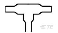
TE Connectivity
301A011-25/86-0
|
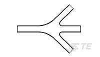
TE Connectivity
462A421-125-0
|
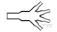
TE Connectivity
562A067-25/86-0
|
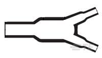
TE Connectivity
382A012-25/42-0
|

TE Connectivity
3SBH1149A2
|
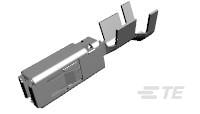
TE Connectivity
1241396-2
|
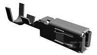
TE Connectivity
1-968859-1
|
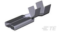
TE Connectivity
1544107-1
|
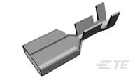
TE Connectivity
1544454-1
|
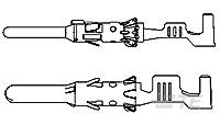
TE Connectivity
1703013-1
|
| Price |
|
|
|
|
|
|
|
|
|
|
|
| RoHS |
|
|
|
|
|
|
|
|
|
|
|
| Lead Status |
|
|
|
|
|
|
|
|
|
|
|
| Special Requirements |
|
Flame Retarded |
Flame Retarded |
Flame Retarded |
Flame Retarded |
|
|
|
|
|
|
| Wire/Cable OD |
|
.16 |
.28 – .7 |
1.18 |
.35 |
|
|
|
|
|
|
| Wire/Cable Main Branch OD |
|
5 |
7.2 – 11.8 |
.79 |
4 |
|
|
|
|
|
|
| Operating Temperature Range |
|
-55 – 105 |
-67 – 347 |
-55 – 105 |
-4 – 140 |
-65 – 125 |
-40 – 150 |
-40 – 130 |
-40 – 125 |
-20 – 85 |
-40 – 130 |
| Material Code |
|
25 |
125 |
25 |
25 |
|
|
|
|
|
|
| Inside Diameter Range (Body) |
|
.14 – .26 |
6.6 – 19.8 |
26.7 – 55.6 |
.24 – .52 |
|
|
|
|
|
|
| Adhesive Code |
|
86 |
S1255-04 |
86 |
42 |
|
|
|
|
|
|
| Material |
|
Modified Elastomer |
Modified Fluoropolymer |
Modified Elastomer |
Modified Elastomer |
|
|
|
|
|
|
| Power Cable Accessory |
|
No |
No |
No |
No |
|
|
|
|
|
|
| Breakout Angle |
|
90 |
30 |
45 |
22.5 |
|
|
|
|
|
|
| Wire/Cable Sm Branch OD |
|
.18 |
.28 – .46 |
.71 |
.18 |
|
|
|
|
|
|
| Molded Part Shape |
|
T Shape |
Slimline, One to Three Cables |
One to Four Cables |
Y Shape |
|
|
|
|
|
|
| Transition Type |
|
T-Transition |
1 to 3 Cables |
1 to 4 Cables |
Y-Transition |
|
|
|
|
|
|
| Inside Diameter Range (Leg 1) |
|
3.6 – 6.6 |
.26 – .52 |
.51 – 1.06 |
3.3 – 6.6 |
|
|
|
|
|
|
| Molded Part Type |
|
Transition |
Breakouts/Transitions |
Transition |
Transition |
|
|
|
|
|
|
| Number of Branches/Legs |
|
2 |
4 |
4 |
2 |
|
|
|
|
|
|
| Adhesive Pre-Coat |
|
Yes |
No |
Yes |
Yes |
|
|
|
|
|
|
| Product Type |
|
Molded Part |
Molded Part |
Molded Part |
Molded Part |
Relay |
|
|
|
|
|
| Material Systems Code |
|
25 |
300 |
25 |
25 |
|
|
|
|
|
|
| Inside Diameter Range (Leg 2) |
|
.14 – .26 |
6.6 – 13.2 |
.51 – 1.06 |
.13 – .26 |
|
|
|
|
|
|
| Government Qualified |
|
No |
No |
No |
No |
|
|
|
|
|
|
| Adhesive Options |
|
/86 Precoat |
None |
/86 Precoat |
/42 Precoat |
|
|
|
|
|
|
| Fluid/Chemical Resistance |
|
Long-term exposure at elevated temps |
Long-Term Exposure at High Temperature |
Long-term exposure at elevated temps |
Long-term exposure at elevated temps |
|
|
|
|
|
|
| Size Code |
|
11 |
21 |
67 |
12 |
|
|
|
|
|
|
| Color |
|
Black |
Black |
Black |
Black |
|
|
|
|
|
|
| Adhesive Type |
|
High Performance Pre-Coat Adhesive |
|
High Performance Pre-Coat Adhesive |
General Purpose Pre-Coat Adhesive |
|
|
|
|
|
|
| Shrink Ratio Type |
|
|
High |
|
|
|
|
|
|
|
|
| Packaging Method |
|
|
Bag/Box |
|
|
|
Reel |
Reel |
|
Reel |
Reel |
| Resistant To |
|
|
Abrasion |
|
|
|
|
|
|
|
|
| Inside Diameter Range (Leg 3) |
|
|
.26 – .52 |
.51 – 1.06 |
|
|
|
|
|
|
|
| Pliancy |
|
|
Flexible |
|
|
|
|
|
|
|
|
| Flammability |
|
|
Flame-Retardant |
|
|
|
|
|
|
|
|
| Comment |
|
|
Contact Raychem for additional adhesive and/or cut off boot length information |
|
|
|
|
|
|
|
|
| Inside Diameter Range (Leg 4) |
|
|
|
.51 – 1.06 |
|
|
|
|
|
|
|
| Coil Polarity Protection Diode |
|
|
|
|
|
Without |
|
|
|
|
|
| Contact Arrangement |
|
|
|
|
|
4 Form C, 4PDT, 4 C/O |
|
|
|
|
|
| Coil Resistance |
|
|
|
|
|
115 |
|
|
|
|
|
| Coil Suppression Diode |
|
|
|
|
|
Without |
|
|
|
|
|
| Mounting Type |
|
|
|
|
|
Printed Circuit Board |
|
|
|
|
|
| Transistor Driver |
|
|
|
|
|
Without |
|
|
|
|
|
| Actuating System |
|
|
|
|
|
DC |
|
|
|
|
|
| Termination Type |
|
|
|
|
|
PC Pins |
|
|
|
|
|
| Coil Magnetic System |
|
|
|
|
|
Non-Polarized, Monostable |
|
|
|
|
|
| Coil Power Rating (DC) |
|
|
|
|
|
1252 |
|
|
|
|
|
| MOSFET Driver |
|
|
|
|
|
Without |
|
|
|
|
|
| Enclosure Type |
|
|
|
|
|
Hermetically Sealed |
|
|
|
|
|
| Coil Latching |
|
|
|
|
|
Without |
|
|
|
|
|
| Input Voltage |
|
|
|
|
|
12 |
|
|
|
|
|
| Vibration |
|
|
|
|
|
30G's, 10 – 3000Hz |
|
|
|
|
|
| Shock |
|
|
|
|
|
75G's, 6ms |
|
|
|
|
|
| Coil Power Measurement |
|
|
|
|
|
Milliwatts |
|
|
|
|
|
| Contact Current Rating |
|
|
|
|
|
2 |
|
|
|
|
|
| Coil Voltage Rating |
|
|
|
|
|
12 |
|
|
|
|
|
| Relay Type |
|
|
|
|
|
Military/Aerospace High Performance |
|
|
|
|
|
| Wire Size Search |
|
|
|
|
|
|
15 |
4 |
12 |
|
18 |
| Interface Plating |
|
|
|
|
|
|
Gold (Au) |
Tin (Sn) |
Tin (Sn) |
Tin (Sn) |
Tin (Sn) |
| Wire Size |
|
|
|
|
|
|
17 – 13 |
4 |
3 – 6 |
2.3 – 4.3 |
.5 – 1 |
| Sealable |
|
|
|
|
|
|
Yes |
Yes |
No |
No |
Yes |
| Typical Current Rating |
|
|
|
|
|
|
22 |
25 |
43 |
20 |
20 |
| Packaging Quantity |
|
|
|
|
|
|
3500 |
2500 |
|
4000 |
3500 |
| Wire Type |
|
|
|
|
|
|
Copper |
Copper |
Copper |
Copper |
Copper |
| Receptacle Style |
|
|
|
|
|
|
180° |
180° |
|
180° |
180° |
| Mating Tab Thickness |
|
|
|
|
|
|
.024 |
.031 |
.031 |
.031 |
|
| Mating Tab Width |
|
|
|
|
|
|
2.8 |
2.8 |
8 |
6.35 |
|
| Terminal & Splice Style |
|
|
|
|
|
|
Receptacle |
Receptacle |
Receptacle |
Receptacle |
Pin |
| Wire Insulation Diameter |
|
|
|
|
|
|
.087 – .118 |
.106 – .146 |
.126 – .173 |
2.7 – 3.7 |
1.2 – 2.1 |
| Termination Method |
|
|
|
|
|
|
Double Crimp |
Crimp |
Crimp |
Crimp |
Crimp |
| Crimp Type |
|
|
|
|
|
|
F-Crimp |
F-Crimp |
F-Crimp |
F-Crimp |
F-Crimp |
| Terminal Transmits |
|
|
|
|
|
|
25 – 40 A (Power) |
25 – 40 A (Power) |
|
0 – 24 A (Low Power) |
0 – 24 A (Low Power) |
| Primary Locking Feature |
|
|
|
|
|
|
Locking Lance |
Locking Lance |
Clean Body |
Clean Body |
Locking Lance |
| Contact Termination Area Plating Material |
|
|
|
|
|
|
Tin (Sn) |
Tin (Sn) |
|
Tin (Sn) |
|
| Agency/Standard |
|
|
|
|
|
|
|
LV214 |
|
|
|
| Mating Pin Diameter |
|
|
|
|
|
|
|
|
|
|
.059 |