|
|
TE Connectivity
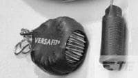
VERSAFIT-KIT-2-COLOR
|
TE Connectivity
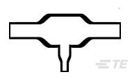
322A112-25-0
|
TE Connectivity
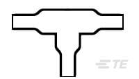
301A011-25/86-0
|
TE Connectivity
462A421-125-0
|

TE Connectivity
562A067-25/86-0
|
TE Connectivity
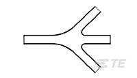
382A012-25/42-0
|
TE Connectivity
1857925-1
|

TE Connectivity
2828522-8
|
TE Connectivity
1-5530841-8
|
TE Connectivity
5645169-4
|
| Price |
|
|
|
|
|
|
|
|
|
|
|
| RoHS |
|
|
|
|
|
|
|
|
|
|
|
| Lead Status |
|
|
|
|
|
|
|
|
|
|
|
| Fluid Type |
|
Aviation Fuel |
|
|
|
|
|
|
|
|
|
| Recovered Wall Thickness (Nominal) |
|
.045 |
|
|
|
|
|
|
|
|
|
| Packaging Method |
|
Piece |
|
|
Bag/Box |
|
|
|
Package |
Box |
|
| Wall Type |
|
Single |
|
|
|
|
|
|
|
|
|
| Operating Temperature Range |
|
-55 – 135 |
-75 – 150 |
-55 – 105 |
-67 – 347 |
-55 – 105 |
-4 – 140 |
-40 – 125 |
|
-67 – 185 |
-67 – 185 |
| Color |
|
White |
Black |
Black |
Black |
Black |
Black |
|
Black |
|
|
| Product Source |
|
UK |
|
|
|
|
|
|
|
|
|
| Shrink Temperature (Min) |
|
70 |
|
|
|
|
|
|
|
|
|
| Cut Length |
|
152.4 |
|
|
|
|
|
|
|
|
|
| Flammability |
|
Highly Flame-Retardant |
|
|
Flame-Retardant |
|
|
|
|
|
|
| Resistant To |
|
Fluids |
|
|
Abrasion |
|
|
|
|
|
|
| Material |
|
Irradiated Modified Polyolefin |
Modified Elastomer |
Modified Elastomer |
Modified Fluoropolymer |
Modified Elastomer |
Modified Elastomer |
|
|
|
|
| Product Family |
|
VERSAFIT |
|
|
|
|
|
|
|
|
|
| Fluid Resistance |
|
Splash Protection |
|
|
|
|
|
|
|
|
|
| Recovery Temperature |
|
90 |
|
|
|
|
|
|
|
|
|
| Low Outgassing |
|
No |
|
|
|
|
|
|
|
|
|
| Shrink Ratio |
|
2:1 |
|
|
|
|
|
|
|
|
|
| Flexibility |
|
Very Flexible |
|
|
|
|
|
|
|
|
|
| Voltage (Max) |
|
.6 |
|
|
|
|
|
|
|
|
|
| Material Systems Code |
|
10 |
25 |
25 |
300 |
25 |
25 |
|
|
|
|
| Applicable Region |
|
Global |
|
|
|
|
|
|
|
|
|
| Inside Diameter Range (Leg 2) |
|
|
3 – 6.6 |
.14 – .26 |
6.6 – 13.2 |
.51 – 1.06 |
.13 – .26 |
|
|
|
|
| Inside Diameter Range (Body) |
|
|
.23 – .52 |
.14 – .26 |
6.6 – 19.8 |
26.7 – 55.6 |
.24 – .52 |
|
|
|
|
| Special Requirements |
|
|
Flame Retarded |
Flame Retarded |
Flame Retarded |
Flame Retarded |
Flame Retarded |
|
|
|
|
| Wire/Cable OD |
|
|
.35 |
.16 |
.28 – .7 |
1.18 |
.35 |
|
|
|
|
| Wire/Cable Main Branch OD |
|
|
.35 |
5 |
7.2 – 11.8 |
.79 |
4 |
|
|
|
|
| Material Code |
|
|
25 |
25 |
125 |
25 |
25 |
|
|
|
|
| Adhesive Pre-Coat |
|
|
No |
Yes |
No |
Yes |
Yes |
|
|
|
|
| Inside Diameter Range (Leg 1) |
|
|
.23 – .52 |
3.6 – 6.6 |
.26 – .52 |
.51 – 1.06 |
3.3 – 6.6 |
|
|
|
|
| Adhesive Options |
|
|
S1017 Separate Adhesive |
/86 Precoat |
None |
/86 Precoat |
/42 Precoat |
|
|
|
|
| Power Cable Accessory |
|
|
No |
No |
No |
No |
No |
|
|
|
|
| Breakout Angle |
|
|
90 |
90 |
30 |
45 |
22.5 |
|
|
|
|
| Wire/Cable Sm Branch OD |
|
|
.18 |
.18 |
.28 – .46 |
.71 |
.18 |
|
|
|
|
| Adhesive Code |
|
|
S1125 |
86 |
S1255-04 |
86 |
42 |
|
|
|
|
| Size Code |
|
|
12 |
11 |
21 |
67 |
12 |
|
|
|
|
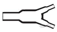
| Molded Part Shape |
|
|
T Shape |
T Shape |
Slimline, One to Three Cables |
One to Four Cables |
Y Shape |
|
|
|
|
| Transition Type |
|
|
T-Transition |
T-Transition |
1 to 3 Cables |
1 to 4 Cables |
Y-Transition |
|
|
|
|
| Adhesive Type |
|
|
Adhesive Purchased Separately |
High Performance Pre-Coat Adhesive |
|
High Performance Pre-Coat Adhesive |
General Purpose Pre-Coat Adhesive |
|
|
|
|
| Molded Part Type |
|
|
Transition |
Transition |
Breakouts/Transitions |
Transition |
Transition |
|
|
|
|
| Number of Branches/Legs |
|
|
2 |
2 |
4 |
4 |
2 |
|
|
|
|
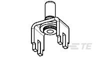
| Product Type |
|
|
Molded Part |
Molded Part |
Molded Part |
Molded Part |
Molded Part |
Contact |
|
Connector Assembly |
Connector Assembly |
| Government Qualified |
|
|
No |
No |
No |
No |
No |
|
|
|
|
| Comment |
|
|
Contact Raychem for additional adhesive and/or cut off boot length information |
|
Contact Raychem for additional adhesive and/or cut off boot length information |
|
|
|
|
|
|
| Fluid/Chemical Resistance |
|
|
Long-term exposure at elevated temps |
Long-term exposure at elevated temps |
Long-Term Exposure at High Temperature |
Long-term exposure at elevated temps |
Long-term exposure at elevated temps |
|
|
|
|
| Shrink Ratio Type |
|
|
|
|
High |
|
|
|
|
|
|
| Inside Diameter Range (Leg 3) |
|
|
|
|
.26 – .52 |
.51 – 1.06 |
|
|
|
|
|
| Pliancy |
|
|
|
|
Flexible |
|
|
|
|
|
|
| Inside Diameter Range (Leg 4) |
|
|
|
|
|
.51 – 1.06 |
|
|
|
|
|
| Contact Current Rating (Max) |
|
|
|
|
|
|
|
50 |
|
3 |
3 |
| Termination Method |
|
|
|
|
|
|
|
Soldering |
|
|
|
| Number of Positions |
|
|
|
|
|
|
|
4 |
|
30 |
98 |
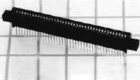
| Connector Mounting Type |
|
|
|
|
|
|
|
Board Mount |
|
Board Mount |
Board Mount |
| Connector & Contact Terminates To |
|
|
|
|
|
|
|
Wire & Cable |
Bus Bar |
Printed Circuit Board |
Printed Circuit Board |
| Connector System |
|
|
|
|
|
|
|
Cable-to-Board |
Wire-to-Bus Bar |
Board-to-Board |
Board-to-Board |
| Contact Base Material |
|
|
|
|
|
|
|
Copper Alloy |
Copper |
Phosphor Bronze |
Phosphor Bronze |
| Contact Size |
|
|
|
|
|
|
|
8 |
9.52 |
|
|
| PCB Mount Orientation |
|
|
|
|
|
|
|
Vertical |
|
Vertical |
Vertical |
| Circuit Application |
|
|
|
|
|
|
|
Power |
|
Power & Signal |
Power & Signal |
| Contact Style |
|
|
|
|
|
|
|
Pin |
CROWN BAND |
|
|
| Voltage Drop |
|
|
|
|
|
|
|
35 |
|
|
|
| Contact Plating Material |
|
|
|
|
|
|
|
Silver over Nickel |
Tin |
|
|
| Current Rating |
|
|
|
|
|
|
|
50 |
250 |
|
|
| Contact Length |
|
|
|
|
|
|
|
|
50.8 |
|
|
| Housing Material |
|
|
|
|
|
|
|
|
Thermoplastic |
Polyester GF |
Polyester GF |
| Insulation Material |
|
|
|
|
|
|
|
|
Thermoplastic |
|
|
| Wire Size |
|
|
|
|
|
|
|
|
168000 |
|
|
| UL Rating |
|
|
|
|
|
|
|
|
Recognized |
|
|
| Mounting Retention |
|
|
|
|
|
|
|
|
No |
|
|
| Connector Style |
|
|
|
|
|
|
|
|
Receptacle |
|
|
| Hot Pluggable |
|
|
|
|
|
|
|
|
No |
|
|
| UL Flammability Rating |
|
|
|
|
|
|
|
|
UL 94V-0 |
UL 94V-0 |
UL 94V-0 |
| Mounting Retention Type |
|
|
|
|
|
|
|
|
Crimp |
|
|
| Number of Power Positions |
|
|
|
|
|
|
|
|
|
60 |
98 |
| Contact Mating Area Plating Thickness |
|
|
|
|
|
|
|
|
|
30 |
30 |
| Contact Termination Area Plating Finish |
|
|
|
|
|
|
|
|
|
Matte |
Matte |
| Housing Color |
|
|
|
|
|
|
|
|
|
Black |
Black |
| PCB Mount Retention Type |
|
|
|
|
|
|
|
|
|
Mounting Ears |
Solder Tail |
| For Use With |
|
|
|
|
|
|
|
|
|
Printed Circuit Board |
Printed Circuit Board |
| Position Keyed |
|
|
|
|
|
|
|
|
|
0 |
0 |
| Contact Termination Area Plating Thickness |
|
|
|
|
|
|
|
|
|
100 |
100 |
| Power Contact Centerline |
|
|
|
|
|
|
|
|
|
.1 |
.1 |
| Panel Mount Feature Type |
|
|
|
|
|
|
|
|
|
Mounting Ears |
|
| Mating Alignment Type |
|
|
|
|
|
|
|
|
|
Keyed |
Keyed |
| Mating Retention |
|
|
|
|
|
|
|
|
|
Without |
Without |
| Contact Type |
|
|
|
|
|
|
|
|
|
Socket |
Socket |
| Number of Dual Positions |
|
|
|
|
|
|
|
|
|
30 |
49 |
| PCB Mount Alignment |
|
|
|
|
|
|
|
|
|
Without |
Without |
| Row-to-Row Spacing |
|
|
|
|
|
|
|
|
|
4.85 |
4.85 |
| Height |
|
|
|
|
|
|
|
|
|
.68 |
.61 |
| End Caps |
|
|
|
|
|
|
|
|
|
Without |
Without |
| Housing Type |
|
|
|
|
|
|
|
|
|
Receptacle |
Receptacle |
| Number of Rows |
|
|
|
|
|
|
|
|
|
2 |
2 |
| Card Slot Depth |
|
|
|
|
|
|
|
|
|
.302 |
.295 |
| Centerline (Pitch) |
|
|
|
|
|
|
|
|
|
2.54 |
2.54 |
| PCB Mount Retention |
|
|
|
|
|
|
|
|
|
With |
With |
| Packaging Quantity |
|
|
|
|
|
|
|
|
|
90 |
|
| Contact Retention |
|
|
|
|
|
|
|
|
|
Without |
Without |
| Operating Voltage |
|
|
|
|
|
|
|
|
|
400 |
400 |
| Termination Method to Printed Circuit Board |
|
|
|
|
|
|
|
|
|
Through Hole - Solder |
Through Hole - Solder |
| Selectively Loaded |
|
|
|
|
|
|
|
|
|
No |
No |
| Contact Underplating Material |
|
|
|
|
|
|
|
|
|
Nickel |
Nickel |
| Mating Alignment |
|
|
|
|
|
|
|
|
|
With |
With |
| Termination Post & Tail Length |
|
|
|
|
|
|
|
|
|
4.75 |
3.18 |
| Termination Post &Tail Length |
|
|
|
|
|
|
|
|
|
.187 |
.125 |
| Mounting Ear Position |
|
|
|
|
|
|
|
|
|
Low |
|
| Contact Termination Area Plating Material |
|
|
|
|
|
|
|
|
|
Tin |
Tin |
| Contact Mating Area Plating Material |
|
|
|
|
|
|
|
|
|
Gold |
Gold |
| Position Locations Omitted |
|
|
|
|
|
|
|
|
|
None |
None |
| PCB Retention Location |
|
|
|
|
|
|
|
|
|
|
5, 6, 31, 32, 41, 42, 93, 94 |
| Type of Connector |
|
|
|
|
|
|
|
|
|
|
Special 18/31 Dual Combination |


