|
|
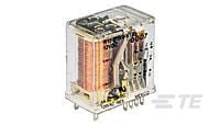
TE Connectivity
R10-R2X2-V700
|
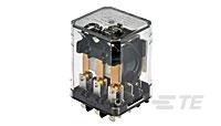
TE Connectivity
KU-14A35-120
|
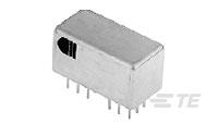
TE Connectivity
LSAW-2C-24B
|
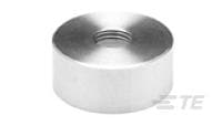
TE Connectivity
G13C
|
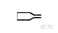
TE Connectivity
204A011-3-0
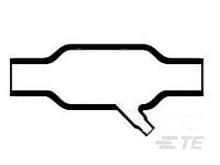
|

TE Connectivity
222A142-3-00-0
|
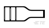
TE Connectivity
342A215-3-0
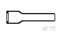
|
TE Connectivity
202D132-3-37-0
|
TE Connectivity
202D221-3/42-0
|
TE Connectivity
322A315-25-0
|
| Price |
|
|
|
|
|
|
|
|
|
|
|
| RoHS |
|
|
|
|
|
|
|
|
|
|
|
| Lead Status |
|
|
|
|
|
|
|
|
|
|
|
| Contact Material |
|
AgCdO |
AgCdO |
|
|
|
|
|
|
|
|
| Contact Current Class |
|
5 – 10 |
5 – 10 |
|
|
|
|
|
|
|
|
| Product Length |
|
.949 |
60 |
|
|
|
|
|
|
|
|
| Product Height |
|
30.2 |
1.402 |
|
|
|
|
|
|
|
|
| Length Class (Mechanical) |
|
20 – 25 |
55 – 65 |
|
|
|
|
|
|
|
|
| Insulation Initial Dielectric Between Open Contacts |
|
500 |
1200 |
|
|
|
|
|
|
|
|
| Insulation Initial Resistance |
|
10000 |
100 |
|
|
|
|
|
|
|
|
| Power Relay Type |
|
Industrial Panel Plug-In |
Industrial Panel Plug-In |
|
|
|
|
|
|
|
|
| Contact Current Rating (Max) |
|
5 |
10 |
|
|
|
|
|
|
|
|
| Product Width |
|
.736 |
1.468 |
|
|
|
|
|
|
|
|
| Coil Power Rating DC |
|
900 |
|
|
|
|
|
|
|
|
|
| Insulation Initial Dielectric Between Contacts & Coil |
|
1000 |
2200 |
|
|
|
|
|
|
|
|
| Relay Mounting Type |
|
Printed Circuit Board |
Panel Mount |
|
|
|
|
|
|
|
|
| Contact Number of Poles |
|
2 |
3 |
|
|
|
|
|
|
|
|
| Terminal Type |
|
PCB-THT |
Solder |
|
|
|
|
|
|
|
|
| Contact Limiting Breaking Current |
|
5 |
10 |
|
|
|
|
|
|
|
|
| Contact Voltage Rating |
|
120 |
240 |
|
|
|
|
|
|
|
|
| Coil Power Rating Class |
|
800 – 1000 |
2 – 3 |
|
|
|
|
|
|
|
|
| Coil Magnetic System |
|
Monostable, DC |
Monostable, AC |
Polarized, Bistable |
|
|
|
|
|
|
|
| Insulation Initial Dielectric Between Adjacent Contacts |
|
1000 |
2200 |
|
|
|
|
|
|
|
|
| Contact Switching Load (Min) |
|
300mA @ 12V |
300mA @ 12V |
|
|
|
|
|
|
|
|
| Coil Resistance |
|
700 |
1700 |
1000 |
|
|
|
|
|
|
|
| Actuating System |
|
DC |
AC |
DC |
|
|
|
|
|
|
|
| Environmental Category of Protection |
|
RTIII |
RTI |
|
|
|
|
|
|
|
|
| Product Weight |
|
40 |
2.988 |
|
|
|
|
|
|
|
|
| Height Class (Mechanical) |
|
30 – 40 |
30 – 40 |
|
|
|
|
|
|
|
|
| Contact Limiting Short-Time Current |
|
5 |
10 |
|
|
|
|
|
|
|
|
| Environmental Ambient Temperature (Max) |
|
167 |
113 |
|
|
|
|
|
|
|
|
| Contact Arrangement |
|
2 Form C (CO) |
3 Form C (CO) |
2 Form C, DPDT, 2 C/O |
|
|
|
|
|
|
|
| Contact Limiting Making Current |
|
5 |
10 |
|
|
|
|
|
|
|
|
| Packaging Method |
|
Package |
Package |
|
Loose Piece |
|
|
|
|
|
|
| Coil Special Features |
|
Sensitive Version |
UL Coil Insulation Class B |
|
|
|
|
|
|
|
|
| Contact Limiting Continuous Current |
|
5 |
10 |
|
|
|
|
|
|
|
|
| Coil Voltage Rating |
|
24 |
120 |
26.5 |
|
|
|
|
|
|
|
| Environmental Ambient Temperature Class |
|
70 – 85 |
0 – 50 |
|
|
|
|
|
|
|
|
| Width Class (Mechanical) |
|
16 – 20 |
30 – 40 |
|
|
|
|
|
|
|
|
| Insulation Initial Dielectric Between Coil & Contact Class |
|
500 – 1000 |
1500 – 2500 |
|
|
|
|
|
|
|
|
| Operating Temperature Range |
|
-55 – 75 |
-45 – 45 |
-65 – 125 |
|
-55 – 135 |
|
-55 – 135 |
-55 – 200 |
-20 – 60 |
-75 – 150 |
| Coil Power Rating AC |
|
|
3 |
|
|
|
|
|
|
|
|
| Input Voltage |
|
|
|
26.5 |
|
|
|
|
|
|
|
| Coil Polarity Protection Diode |
|
|
|
Without |
|
|
|
|
|
|
|
| Coil Latching |
|
|
|
Double |
|
|
|
|
|
|
|
| Contact Current Rating |
|
|
|
2 |
|
|
|
|
|
|
|
| Coil Suppression Diode |
|
|
|
Without |
|
|
|
|
|
|
|
| Transistor Driver |
|
|
|
Without |
|
|
|
|
|
|
|
| Product Type |
|
|
|
Relay |
Accessory |
|
|
|
|
|
|
| MOSFET Driver |
|
|
|
Without |
|
|
|
|
|
|
|
| Relay Type |
|
|
|
Military/Aerospace High Performance |
|
|
|
|
|
|
|
| Enclosure Type |
|
|
|
Hermetically Sealed |
|
|
|
|
|
|
|
| Coil Power Rating (DC) |
|
|
|
702 |
|
|
|
|
|
|
|
| Vibration |
|
|
|
20G's, 10 – 2000Hz |
|
|
|
|
|
|
|
| Mounting Type |
|
|
|
Plain Case |
|
|
|
|
|
|
|
| Termination Type |
|
|
|
PC Pins |
|
|
|
|
|
|
|
| Shock |
|
|
|
100G's, 6ms |
|
|
|
|
|
|
|
| Coil Power Measurement |
|
|
|
Milliwatts |
|
|
|
|
|
|
|
| Cap Height |
|
|
|
|
8.001 |
|
|
|
|
|
|
| Color |
|
|
|
|
Chromed Brass |
|
|
|
|
|
|
| Style |
|
|
|
|
Round |
|
|
|
|
|
|
| Finish |
|
|
|
|
Plain |
|
|
|
|
|
|
| Cap Diameter |
|
|
|
|
.728 |
|
|
|
|
|
|
| Thread Size |
|
|
|
|
1/4 – 40 UNS-2B |
|
|
|
|
|
|
| Tactile |
|
|
|
|
No |
|
|
|
|
|
|
| For Use With |
|
|
|
|
C13 Cap |
|
|
|
|
|
|
| Illuminated |
|
|
|
|
No |
|
|
|
|
|
|
| Guard Color |
|
|
|
|
Chromed Brass |
|
|
|
|
|
|
| Process Sealed |
|
|
|
|
No |
|
|
|
|
|
|
| Guard Finish |
|
|
|
|
Plain |
|
|
|
|
|
|
| Accessory Type |
|
|
|
|
Guard |
|
|
|
|
|
|
| Adhesive Options |
|
|
|
|
|
S1006 Separate Adhesive, -55°C to +135°C (-67°F to + 275°F) |
|
|
None |
/42 Precoat, -20 – 60°C (-4 – 140°F) |
|
| Adhesive Pre-Coat |
|
|
|
|
|
No |
No |
No |
No |
Yes |
No |
| Power Cable Accessory |
|
|
|
|
|
No |
No |
|
No |
No |
|
| Approved Standards |
|
|
|
|
|
DEF Std 59-97 Issue 3 Type DA |
SAE AS81765/1 Type I |
|
SAE AS81765/1 Type I |
BS-G-198-5-DA |
|
| Wire/Cable Outside Diameter |
|
|
|
|
|
6 mm |
|
|
|
12 mm |
|
| Connector or Backshell Outside Diameter |
|
|
|
|
|
9 mm |
|
|
|
|
|
| Molded Part Type |
|
|
|
|
|
Molded Boot |
Molded Boot |
Transition |
Molded Boot |
Molded Boot |
Transition |
| Material Systems Code |
|
|
|
|
|
10 |
10 |
10 |
10 |
10 |
25 |
| Lipped |
|
|
|
|
|
No |
No |
No |
Yes |
Yes |
No |
| Adhesive Type |
|
|
|
|
|
Adhesive Purchased Separately |
Adhesive Purchased Separately |
|
Adhesive Purchased Separately |
General Purpose Pre-Coat Adhesive |
|
| Molded Part Shape |
|
|
|
|
|
Straight |
|
45° |
|
|
90° |
| Inside Diameter as Supplied |
|
|
|
|
|
|
32.5 |
|
1.12 |
|
|
| Government Qualified |
|
|
|
|
|
|
No |
|
No |
No |
|
| Material |
|
|
|
|
|
|
Modified Polyolefin |
Semi-Rigid Modified Polyolefin |
Modified Polyolefin |
Modified Polyolefin |
Fluid Resistant Modified Elastomer |
| Cable Diameter Range |
|
|
|
|
|
|
.68 – 1.28 |
|
|
7.4 – 16 |
|
| Fluid/Chemical Resistance |
|
|
|
|
|
|
|
Occasional exposure to fluids |
|
Suitable for occasional exposure to fluids |
Suitable for long term fluid exposure at elevated temperatures |
| Flammability |
|
|
|
|
|
|
|
Flame-Retardant |
|
|
Flame-Retardant |
| Entry Size (Solid or Fixed Adapter) |
|
|
|
|
|
|
|
|
|
4 |
|
| Entry Size (Spin Coupling Adapter) |
|
|
|
|
|
|
|
|
|
6 – 7 |
|


