|
|
TE Connectivity
MS14-2Y
|

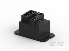
TE Connectivity
5-1415520-1
|
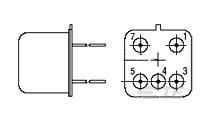
TE Connectivity
T9CP5A54-120
|

TE Connectivity
STD12W-V
|
TE Connectivity
PS00XSS60
|

TE Connectivity
PE0SXSH6A
|
TE Connectivity
PE000SS60
|

TE Connectivity
PE0S0DSX0
|
TE Connectivity
PE0SSS000
|
TE Connectivity
6EL1SM
|
| Price |
|
|
|
|
|
|
|
|
|
|
|
| RoHS |
|
|
|
|
|
|
|
|
|
|
|
| Lead Status |
|
|
|
|
|
|
|
|
|
|
|
| Packaging Style |
|
Mini .100in Grid |
|
|
|
|
|
|
|
|
|
| Output Type |
|
DC |
|
|
|
.187" FASTON |
.187" FASTON |
.187" FASTON |
.187" FASTON |
.187" FASTON |
.110" FASTON |
| Relay Mounting Type |
|
Printed Circuit Board |
Printed Circuit Board |
Quick Connect |
|
|
|
|
|
|
|
| Dimensions (L x W x H) (Approximate) |
|
.37 x .335 x .275 |
|
|
|
|
|
|
|
|
|
| Insulation Initial Dielectric Between Contacts & Coil |
|
1000 |
4000 |
2500 |
|
|
|
|
|
|
|
| Power Relay Type |
|
Solid State |
Standard |
Standard |
|
|
|
|
|
|
|
| Shock |
|
1500G's, .5ms |
|
|
|
|
|
|
|
|
|
| Output Voltage Rating (DC Relays) |
|
200 |
|
|
|
|
|
|
|
|
|
| Output Current Rating |
|
0.18 |
|
|
|
|
|
|
|
|
|
| Screening Level |
|
Y |
|
|
|
|
|
|
|
|
|
| Input Voltage |
|
3.8 – 32 |
|
|
|
|
|
|
|
|
|
| R-Switch & slimSSR Relays |
|
No |
|
|
|
|
|
|
|
|
|
| Enclosure Type |
|
Sealed |
|
|
|
|
|
|
|
|
|
| Operating Temperature Range |
|
-55 – 105 |
|
|
|
-10 – 40 |
-10 – 40 |
-10 – 40 |
-10 – 40 |
-10 – 40 |
-10 – 40 |
| Terminal Type |
|
|
PCB-THT |
Quick Connect |
|
|
|
|
|
|
|
| Contact Current Class |
|
|
10 – 20 |
20 – 30 |
|
|
|
|
|
|
|
| Contact Current Rating (Max) |
|
|
16 |
30 |
|
|
|
|
|
|
|
| Height Class (Mechanical) |
|
|
15 – 16 |
20 – 35 |
|
|
|
|
|
|
|
| Contact Limiting Breaking Current |
|
|
16 |
30 |
|
|
|
|
|
|
|
| Contact Switching Voltage (Max) |
|
|
400 |
277 |
|
|
|
|
|
|
|
| Coil Power Rating Class |
|
|
300 – 400 |
|
|
|
|
|
|
|
|
| Insulation Special Features |
|
|
Tracking Index of Relay Base PTI250 |
6000V Initial Surge Withstand Voltage between Contacts & Coil |
|
|
|
|
|
|
|
| Contact Voltage Rating |
|
|
250 |
277 |
|
|
|
|
|
|
|
| Coil Power Rating DC |
|
|
400 |
|
|
|
|
|
|
|
|
| Insulation Creepage Between Contact & Coil |
|
|
8 |
.25 |
|
|
|
|
|
|
|
| Packaging Method |
|
|
Tray |
Tray/Box |
Strip |
|
|
|
|
|
|
| Environmental Category of Protection |
|
|
RTII |
RTII |
|
|
|
|
|
|
|
| Product Weight |
|
|
20 |
|
|
|
|
|
|
|
|
| Contact Number of Poles |
|
|
1 |
2 |
|
|
|
|
|
|
|
| Product Length |
|
|
29 |
50.3 |
|
|
|
|
|
|
|
| Insulation Clearance Between Contact & Coil |
|
|
.315 |
3.18 |
|
|
|
|
|
|
|
| Length Class (Mechanical) |
|
|
25 – 30 |
50 – 55 |
|
|
|
|
|
|
|
| Contact Switching Load (Min) |
|
|
500mA @ 12V |
1000mA @ 5V |
|
|
|
|
|
|
|
| Coil Magnetic System |
|
|
Monostable, DC |
Monostable, AC |
|
|
|
|
|
|
|
| Insulation Creepage Class |
|
|
5.5 – 8 |
5.5 – 8 |
|
|
|
|
|
|
|
| Insulation Initial Dielectric Between Open Contacts |
|
|
1000 |
1500 |
|
|
|
|
|
|
|
| Coil Resistance |
|
|
360 |
2800 |
|
|
|
|
|
|
|
| Product Width |
|
|
12.7 |
27.4 |
|
|
|
|
|
|
|
| Coil Special Features |
|
|
UL Coil Insulation Class F |
UL Coil Insulation Class F |
|
|
|
|
|
|
|
| Insulation Initial Dielectric Between Coil & Contact Class |
|
|
3500 – 4000 |
1500 – 2500 |
|
|
|
|
|
|
|
| Environmental Ambient Temperature Class |
|
|
85 – 105 |
-40 – 70 |
|
|
|
|
|
|
|
| Environmental Ambient Temperature (Max) |
|
|
105 |
70 |
|
|
|
|
|
|
|
| Insulation Clearance Class |
|
|
5 – 8 |
2.5 – 4 |
|
|
|
|
|
|
|
| Contact Limiting Making Current |
|
|
25 |
30 |
|
|
|
|
|
|
|
| Coil Voltage Rating |
|
|
12 |
120 |
|
|
|
|
|
|
|
| Width Class (Mechanical) |
|
|
12 – 16 |
25 – 30 |
|
|
|
|
|
|
|
| Contact Material |
|
|
AgNi90/10 |
AgSnOlnO |
|
|
|
|
|
|
|
| Contact Arrangement |
|
|
1 Form A (NO) |
1 Form C (CO) |
|
|
|
|
|
|
|
| Product Height |
|
|
.63 |
27.9 |
|
|
|
|
|
|
|
| Contact Limiting Continuous Current |
|
|
16 |
30 |
|
|
|
|
|
|
|
| Contact Limiting Short-Time Current |
|
|
16 |
30 |
|
|
|
|
|
|
|
| Coil Power Rating AC |
|
|
|
1600 |
|
|
|
|
|
|
|
| Relay Termination Type |
|
|
|
.25 x .032 Quick Connect Terminals |
|
|
|
|
|
|
|
| Insulation Initial Resistance |
|
|
|
1000 |
|
|
|
|
|
|
|
| Printed Marking Color |
|
|
|
|
Black |
|
|
|
|
|
|
| Marker Cut |
|
|
|
|
Straight |
|
|
|
|
|
|
| Marker Material |
|
|
|
|
Polyoxymethylene |
|
|
|
|
|
|
| Packaging Quantity |
|
|
|
|
321 |
|
|
|
|
|
|
| Compatible Cable Diameter |
|
|
|
|
4.5 – 6 |
|
|
|
|
|
|
| Printed Marking |
|
|
|
|
V |
|
|
|
|
|
|
| Marker Style |
|
|
|
|
Snap-On |
|
|
|
|
|
|
| Marker Size |
|
|
|
|
STD 12 |
|
|
|
|
|
|
| Marker Color |
|
|
|
|
White |
|
|
|
|
|
|
| Leakage Current (Max) (250VAC, 50Hz) |
|
|
|
|
|
500 |
5 |
500 |
5 |
|
|
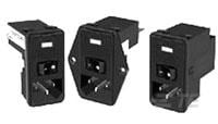
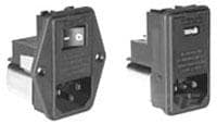
| Type of Connector |
|
|
|
|
|
IEC 320/C-14 |
IEC 60320-1 C-14 |
IEC 320/C-14 |
IEC 60320-1 C-14 |
IEC 320/C-14 |
IEC 320/C-14 |
| Ground Choke Option |
|
|
|
|
|
No |
No |
No |
No |
No |
No |
| Mount Angle |
|
|
|
|
|
Vertical |
Vertical |
Vertical |
Vertical |
Vertical |
Vertical |
| Switch Type |
|
|
|
|
|
None |
DPST |
None |
DPST |
DPST |
DPST |
| Fuse Options |
|
|
|
|
|
Single |
Single |
Single |
Dual |
Single |
Dual |
| Shield Style |
|
|
|
|
|
None |
Filter Shield |
None |
None |
None |
|
| Voltage Selection |
|
|
|
|
|
2-Voltage |
2-Voltage |
Single |
Single |
2-Voltage |
Single |
| Current Rating |
|
|
|
|
|
6 |
6 |
6 |
10 |
|
6 |
| Leakage Current (Max) (120VAC, 60Hz) |
|
|
|
|
|
250 |
2 |
250 |
2 |
|
|
| Filter Type |
|
|
|
|
|
Power Entry Module |
Power Entry (Filtered/Unfiltered) |
Power Entry Module |
Power Entry (Filtered/Unfiltered) |
Power Entry Module |
Power Entry Module |
| Ground Option |
|
|
|
|
|
None |
None |
None |
None |
None |
None |
| Filtered |
|
|
|
|
|
Yes |
Yes |
Yes |
Yes |
No |
No |
| Extender Options |
|
|
|
|
|
None |
None |
None |
None |
None |
|
| Input Voltage Select |
|
|
|
|
|
Dual AC (Series/Parallel) |
Dual AC (Series/Parallel) |
Single AC |
Single AC |
Dual AC (SMPS) |
|
| Mount Style |
|
|
|
|
|
Snap-In |
Flanged |
Flanged |
Flanged |
Flanged |
Flanged |
| Input Type |
|
|
|
|
|
IEC |
IEC |
IEC |
IEC |
IEC |
IEC |
| For Use With |
|
|
|
|
|
|
P Series |
|
P Series |
|
|
| Level Of Filtering |
|
|
|
|
|
|
Inductor & Capacitor |
|
Inductor & Capacitor |
|
|
| Panel Thickness Range |
|
|
|
|
|
|
.031 – .079 |
.127 – 1 |
.031 – .079 |
.127 – 1 |
|
| Voltage (Max) |
|
|
|
|
|
|
230 |
250 |
230 |
250 |
120 |
| Accessory Type |
|
|
|
|
|
|
Fuse Clip |
|
Fuse Clip |
|
|
| Comment |
|
|
|
|
|
|
|
|
|
|
Voltage Fixed |


